To tell if your coax is bad, work up a ladder: look at the cable and connectors, meter it for a short or an open, substitute a known-good length, then measure loss with a coax tester or NanoVNA. Most faults are mechanical or moisture, and most people find them in the first two steps before they touch an instrument.
The whole job takes about half an hour on the bench. The hard part is resisting the urge to swap the radio, the tuner, or the grounding first.
Table of Contents
- 1What You Need
- 2Know Your Cable Type First
- 3Step-by-Step: How to Tell If Your Coax Is Bad With Five Tests
- 41. Inspect the Coax and Connectors for Visual Signs of a Bad Cable
- 52. Check for a Short or Open with a Multimeter
- 63. Test the Cable with a Coax Tester or NanoVNA
- 74. Substitute a Known-Good Cable
- 85. Confirm the Fault with a Controlled Antenna Test
- 9Common Mistakes
- 10Frequently Asked Questions
- 11Does a high SWR reading prove my coax is bad?
- 12Can I use a multimeter to test coax cable?
- 13Why does a brand new coax cable still give me problems?
- 14How does moisture get into coax cable, and can that cable be saved?
- 15Should I repair damaged coax or replace the whole run?
- 16How long does coaxial cable last?
- 17Conclusion
What You Need
You can start with nothing but your eyes and a flashlight. Each step up the ladder adds one instrument, and every instrument answers a question the one below it cannot.
| Test | Tool | What it detects | Healthy result | Fault result |
|---|---|---|---|---|
| Visual inspection | Flashlight, magnifier | Cracked jacket, water entry, corroded connector, kinks | Dry, clean, unbroken jacket | Split foam, green braid, swollen seal |
| DC continuity | Multimeter on ohms | Shorts between center conductor and shield, broken center conductor | Low single-digit resistance end to end, open to the shield | Near 0 ohm to the shield, or infinite end to end |
| Go/no-go tester | Coax cable tester | Presence of RF and gross shorts | Tone or LED on both ends | Silent, or tone on the shield alone |
| Loss measurement | NanoVNA or antenna analyzer | Insertion loss, return loss, capacitance, where the fault sits | Loss matches the cable’s published figure for that length | Loss far above spec, or a sharp dip and rise |
| Distance to fault | TDR or cable tester with TDR function | Exact distance to a short or impedance break | Flat trace to the far end | Step or spike partway along the run |
A known-good 50 ohm load matters more than it looks. Without one, every loss number you take includes the reflection from whatever you happen to be plugged into, and you end up blaming the cable for somebody else’s mismatch.
You also want the right test lead. A coax adapter that turns your multimeter probes into a BNC or F connector, plus a few hand tools if you suspect a loose connector.
Know Your Cable Type First
You cannot judge a reading without knowing what the cable is supposed to do. The jacket is usually printed, and RG6 versus RG59 is the difference that trips people up most.
| Type | Impedance | Typical loss per 100 ft at 100 MHz | Normal use |
|---|---|---|---|
| RG59 | 75 ohm | About 6 dB | Older CCTV and satellite runs |
| RG6 | 75 ohm | About 5 dB | OTA TV, cable internet, satellite, HF |
| RG8X | 50 ohm | About 4.5 dB | Ham radio HF and VHF feed lines |
| LMR-400 | 50 ohm | About 2.7 dB | Long runs and higher power |
Loss runs roughly linearly with length at a given frequency, so a 200 foot run should show close to double the per-100-foot figure. If it shows much more, you have a fault, not just a long cable.
Step-by-Step: How to Tell If Your Coax Is Bad With Five Tests
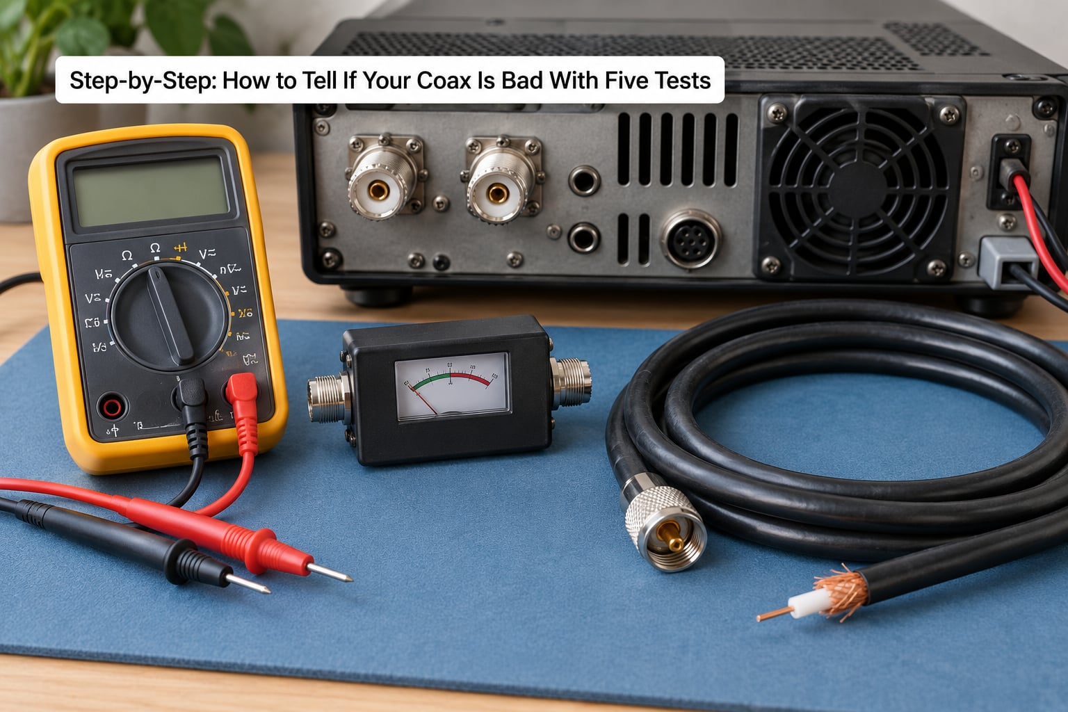
1. Inspect the Coax and Connectors for Visual Signs of a Bad Cable
Visual signs come first because they cost nothing and they catch most real faults. Look for these seven, then check the connectors separately.
- Cracked, split, or hardened outer jacket
- Water or a dark wet patch at a connector end
- Green or white corrosion on a BNC, F-type, or PL-259 shell
- Braid that frays, slips, or pulls back from the connector
- A pinched or crushed section, often near a staple or a door track
- A sharp kink past the cable’s bend radius
- Chalking, discoloration, or brittleness from years of UV exposure
Unplug everything before you handle it. Never probe a connector that is still attached to a transceiver, and never test a run you do not understand while it is connected to gear you care about.
At each connector, unscrew it and look straight into the mating face. You want to see a clean, bright center pin, braid that fills the barrel evenly, and a dielectric that sits flush with no foam pulled back into the cable.
On the outside, check the strain relief where the jacket meets the crimp. A jacket that will slide in either direction means the crimp did not grab it, and that connection will fail at the first bump of weather.
Run your thumb along the whole length, indoors and out. If the fault is intermittent, this pass usually finds the pinch point where the signal dies.
2. Check for a Short or Open with a Multimeter
A multimeter tells you whether you have a short or an open, and it cannot tell you anything about impedance, loss, or signal quality. Knowing that limit up front saves a lot of confusion.
- Disconnect both ends. Set the meter to the lowest ohms range you have.
- Touch the probes together and note the reading. That is your probe and lead resistance, usually a fraction of an ohm.
- Hold one probe on the center pin of one connector and the other on the metal shell or braid.
- Read the resistance. Then turn the connector in your fingers while the probes stay put.
- Move to the far connector and repeat the center-to-shield check on that end.
- Now bridge the center pin to the center pin across the full length, and then the shell to the shell.
What those readings mean:
| Reading | What it means | What to do |
|---|---|---|
| 0 to about 1 ohm between center and shield | Hard short. Damaged dielectric, water, or a crushed cable | Bisect the run and find the section |
| Resistance climbs, drops, or beeps intermittently when you wiggle the connector | Intermittent fault, usually a loose crimp or a wet connector | Re-terminate or replace that end |
| Thousands of ohms to megohms between center and shield | Normal for most coax. The dielectric isolates the two conductors | Nothing, this is a pass |
| Over-range or infinite from center to center | Open circuit. Broken center conductor somewhere along the run | Bisect the run |
| Under 1 ohm from center to center | Healthy. Very low DC resistance through the conductor | Nothing, this is a pass |
Here is where a lot of cable-vendor advice goes wrong. Plenty of pages say a good coax should read about 75 ohms on a multimeter. A multimeter applies DC, and DC resistance has nothing to do with the 50 or 75 ohm characteristic impedance your antenna system actually runs at. Expecting 75 ohm gets you a false failure on a perfectly good cable.
A low single-digit reading end to end, plus a high reading to the shield, is the correct pass condition. Anything you see on the capacitance range is a bonus: healthy coax between 20 and 80 pF per meter is typical, so a reading several times higher points at moisture in the dielectric.
3. Test the Cable with a Coax Tester or NanoVNA
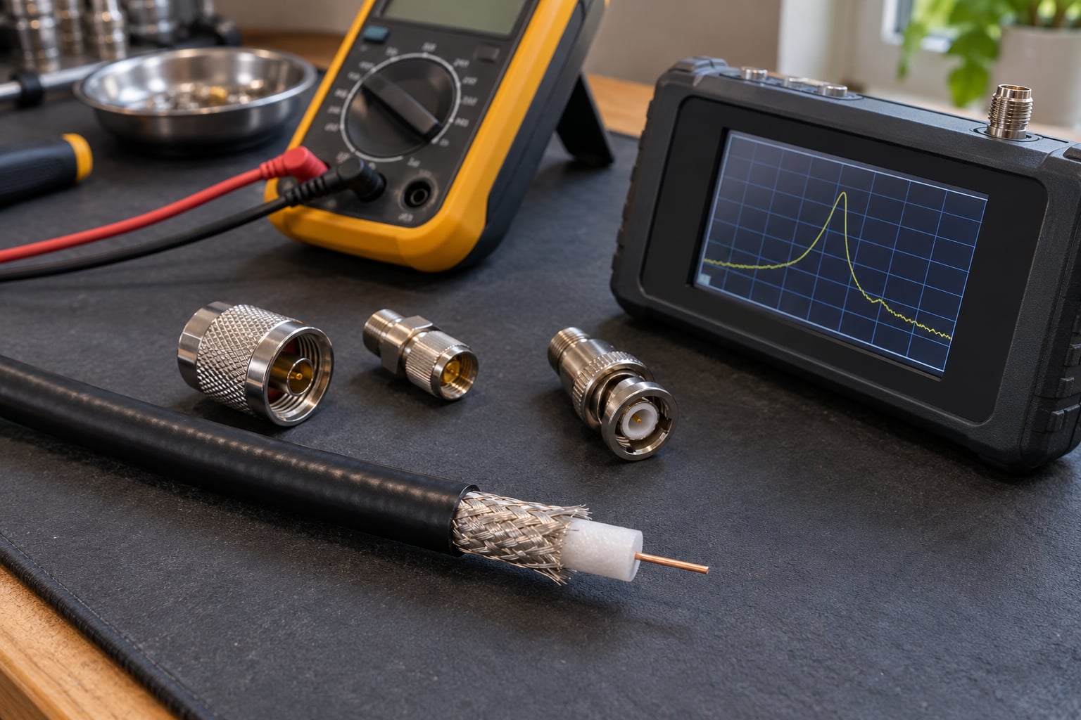
This is the step that turns guesswork into a number. A coax cable tester gives you a fast go or no-go, and a vector network analyzer such as a NanoVNA gives you loss, return loss, and the shape of the fault.
Set the analyzer to your band of interest, terminate the far end in a quality 50 ohm load, and read the insertion loss at a specific frequency. Compare that figure against the cable type table above, scaled to your length.
Measure a short known-good cable first. That gives you a reference including your connectors and your load, so the second measurement isolates the suspect run.
What a bad cable looks like on screen: loss several times higher than the reference, return loss collapsing badly at one frequency, or a curve that swoops into a deep minimum and climbs back. A straight, smooth cable has a flat trace. A damaged one has a step in it.
That step is the useful part, because a fault partway along a cable shows up as an impedance bump at roughly the point where the wave velocity changes. A NanoVNA at one end with a 50 ohm load at the other can tell you not just that the cable is bad, but roughly where. For exact distance, a dedicated distance-to-fault meter or a TDR function reads the reflection directly.
Frequency range matters when you compare readings. A cable can look fine at 14 MHz and terrible at 1.2 GHz, because losses scale with frequency and any small defect scales faster. Always record the frequency next to the number.
Check connector installation while you have it set up. A PL-259 with a dull, loose crimp, or an F-type connector whose center pin sits below the surrounding dielectric, adds return loss that looks exactly like a bad cable.
4. Substitute a Known-Good Cable
Substitution is the cheapest decisive test there is, and it settles arguments between the cable and everything else in the chain.
Unplug the suspect run and connect a short known-good jumper of the same connector type in its place. For a mast-mounted antenna, run the radio straight to the antenna with a short jumper and do a quick check there.
One amateur radio operator on r/amateurradio lost half his bands after heavy snow and freeze-thaw cycles, and swapping radios, tuners, and grounding changed nothing. He connected the rig directly at the antenna with a short jumper, performance came back immediately, and wiggling the buried run near the house entry made the braid short. The cable was the whole problem.
Compare these four signals before and after the swap:
- SWR drops and stabilizes
- Forward power stays the same but reflected power falls
- Received signals get stronger and quieter
- Pixelation, dropouts, and modem sync errors stop
What substitution cannot do is clear the antenna, the splitter, or the transceiver. If a short jumper at the antenna fixes things, the fault is somewhere in the run between the radio and that point. If nothing changes, the cable is innocent and the antenna or the radio deserves the next look.
5. Confirm the Fault with a Controlled Antenna Test
A controlled test means one variable at a time and a written baseline. Write down the readings before you change anything, then again after.
Start with the far end in a known-good 50 ohm dummy load, at the lowest power your rig will make stable readings. Record SWR at that power, then move up. An SWR that climbs sharply with power is a strong hint of a lossy or partially shorted cable, because the fault is dissipating reflected power as heat.
Do the same measurement on two or three bands rather than one. A genuine cable fault shows up on multiple bands; a connector or antenna problem often moves around with frequency.
Check receive too. Turn the AGC and compare the noise floor and signal strength with the suspect cable and the replacement. A cable with moisture in it often passes transmit and fails receive first, because a wet dielectric leaks more on the weaker inbound signal.
Map the symptom to the likely cause before you order anything:
| Symptom | Most likely cause | Confirm with |
|---|---|---|
| Pixelated TV, some channels only | Corroded F connector or marginal crimp at the aerial | Inspect the connector, swap the lead |
| Internet drops or slow speeds | Braided shield damaged, or a splitter losing margin | Continuity test, then bypass the splitter |
| SWR suddenly high with no antenna change | Coax fault, usually water at a connector or a crushed section | Substitution, then NanoVNA loss check |
| SWR reading jumps around wildly | Intermittent fault. A short or open produces chaos, not a clean number | Wiggle test at suspect points |
| No signal at all | Open circuit, or a totally dead cable | Multimeter end to end |
| Fault comes and goes with weather | Moisture intrusion at a failed weather seal | Open the connector and look for water |
Erratic SWR is worth calling out on its own. A short, an open, or a badly kinked cable does not produce a stable high reading, it produces a moving one, because the fault point is electrically unstable.
If you keep transmitting into a serious mismatch, the reflected power turns into heat inside the coax and at the amplifier output. That is how a marginal fault ends up as a damaged transceiver final, so drop the power or stop transmitting while you diagnose.
Common Mistakes
Testing while the radio is powered. Unplug the transceiver and any powered distribution equipment first. A meter across a live connector gives you a reading that means nothing and a shock that means something.
Measuring without disconnecting the cable from everything. The radio, tuner, preamp, and antenna are all parallel paths. Your meter sees them too. Disconnect both ends, every time.
Expecting 75 ohms on the multimeter. Already covered above, and it is the single most repeated piece of bad advice on this topic. DC resistance is not impedance.
Confusing normal antenna resistance with a short. A resonant antenna legitimately presents a very low resistance at one frequency, and many antennas look like near-zero ohms to a DC meter. Only a center-to-shield reading on a disconnected cable means anything.
Ignoring the connectors. More coax faults live in the terminations than in the middle of the run. A corroded F connector or a braid that slipped under the crimp will produce every symptom of a broken cable.
Changing variables mid-comparison. If you swap the cable and also move the antenna, you learn nothing. One change, one set of readings, written down.
Replacing good coax first. Test the feed line, the antenna, the balun, the connectors, and the installation before you pull a run. Cable that was crushed by a staple or bent past its radius was installed wrong, and the new cable will meet the same fate.
Judging from a single noisy reading. Take the measurement three times. On HF, propagation changes and a noisy band will move your SWR for reasons that have nothing to do with your cable.
One more that catches beginners: forgetting that coax carries the RF current on the outside of the shield. A cable routed alongside a metal roof, a chimney, or a tower without spacing can read as damaged when it is behaving normally. Change the routing before you condemn the cable.
Frequently Asked Questions
Does a high SWR reading prove my coax is bad?
No. High SWR means the impedance your radio sees is not matched to 50 ohms, and that can come from the coax, the connectors, the antenna, the balun, or a mounting change. Prove the cable first by substituting a known-good jumper of the same length and connectors. If SWR stays high with good coax connected, the cable is not the fault. Erratic readings that move as you waffle the cable point harder at a real cable fault than a mismatch does.
Can I use a multimeter to test coax cable?
Yes, for the two faults that matter most: a short between the center conductor and the shield, and an open in the center conductor. Disconnect both ends, check probe resistance first, then read center-to-shield and center-to-center. Low single-digit ohms from center to center with a high reading to the shield is a pass. A multimeter cannot measure impedance, loss, or signal quality, so it cannot replace an analyzer on a cable that tests electrically fine but works badly.
Why does a brand new coax cable still give me problems?
Usually because the fault is not in the cable you just bought. It is in the connector you attached, the antenna, the balun, the mounting, or the coax you already had. A badly crimped or incompletely seated connector produces the same symptoms as a broken cable. Test the new run end to end before you install it, re-seat every connector, and confirm the antenna and balun before blaming a fresh length of RG6.
How does moisture get into coax cable, and can that cable be saved?
Water enters through a cracked jacket, a missing or stripped weather seal, an unsealed connector, or a cable end left open in the rain. Once the foam dielectric is wet it rarely dries out, because the shield traps the moisture. One user tested a homemade cable left unsealed and it read shorted; re-terminating the connectors did not help, which points at the dielectric rather than the connectors. Such a cable is normally scrap.
Should I repair damaged coax or replace the whole run?
Replace the cable if the jacket is split, crushed, kinked past its bend radius, or wet inside, since none of those are repairable. Replacing a single connector is worth doing when the cable itself is sound and the fault is a corroded shell, a stripped braid, or a loose crimp. For buried or in-wall runs that will be a dig or a chase to reach, cutting the run at the fault and re-terminating both sides is often faster than replacing the whole thing.
How long does coaxial cable last?
It depends almost entirely on installation and environment rather than the calendar. Indoors, out of the way, good coax often lasts for decades. Outdoors or buried, expect far less once UV exposure, freeze-thaw cycles, soil moisture, and rodents are involved. Forum consensus is that coax rarely fails on its own unless it was damaged by conditions or installed badly, which is why finding the mechanical cause matters more than the age of the cable.
Conclusion
Start by unplugging the run and looking at it. Cracked jacket, corroded connector, water at the end, a crushed or sharply kinked section. Those account for most failures, and the fix is usually a connector or a short replacement length.
If it looks fine, meter it. Low resistance from center to center and a high reading to the shield means the cable is electrically sound, and your problem is somewhere else in the system. Then substitute a known-good jumper before you go shopping, and reach for a NanoVNA or distance-to-fault reading only when the cheap tests point somewhere you cannot reach by hand.
Coax is one link in a chain that includes the antenna, the balun, the connectors, the mounting, and the transceiver. Diagnose it alongside them, one variable at a time, and keep the power down until the readings stop jumping.