Coax loss is the RF power your feedline absorbs and turns into heat between the radio and the antenna. That lost power never reaches the antenna to radiate, and on receive the same cable weakens both the signal and the noise, which means the signal-to-noise ratio barely moves. The bigger the run, the higher the frequency and the worse the SWR, the more it costs you.
It is worth saying up front that coax loss is usually less dramatic than forum posts imply. A 3 dB loss sounds like a disaster until you realise it means half the power. Half your signal sounds serious too, until you remember that cutting a 3 dB loss down to 1 dB only gets you back 2 dB of range, and most stations never notice 2 dB at all.
The rest of this guide walks through what physically causes the loss, how the mismatch on the antenna end multiplies it, how to work the numbers out for your own run, and how to tell whether the cable you already own is still doing its job.
Table of Contents
- 1What Is Coax Loss?
- 2Where coax loss physically comes from
- 3How Coax Loss Changes the Signal
- 4Why the signal-to-noise ratio stays put on receive
- 5Why Cable Type Matters at Different Frequencies
- 6Construction details that matter
- 7How Impedance Mismatch Makes Coax Loss Matter More
- 8Where the SWR myths come from
- 9How to Calculate the Loss in Your Feed Line
- 10What Coax Loss Means for Receiving
- 11How coax loss affects antenna performance during weak-signal reception
- 12What Coax Loss Means for Transmitting
- 13How to Choose the Right Coax for Your Antenna
- 14When RG-58 is genuinely fine
- 15Practical Ways to Reduce Coax Loss
- 16How to Test an Installed Feed Line
- 17Frequently Asked Questions
- 18Does coax loss change the antenna’s radiation pattern?
- 19Does low-loss coax improve the receive range of a shortwave radio?
- 20Can an antenna tuner eliminate coax loss?
- 21How much coax loss is acceptable for amateur radio?
- 22Should I use lower-loss coax or move the antenna closer to the station?
- 23Conclusion
What Is Coax Loss?
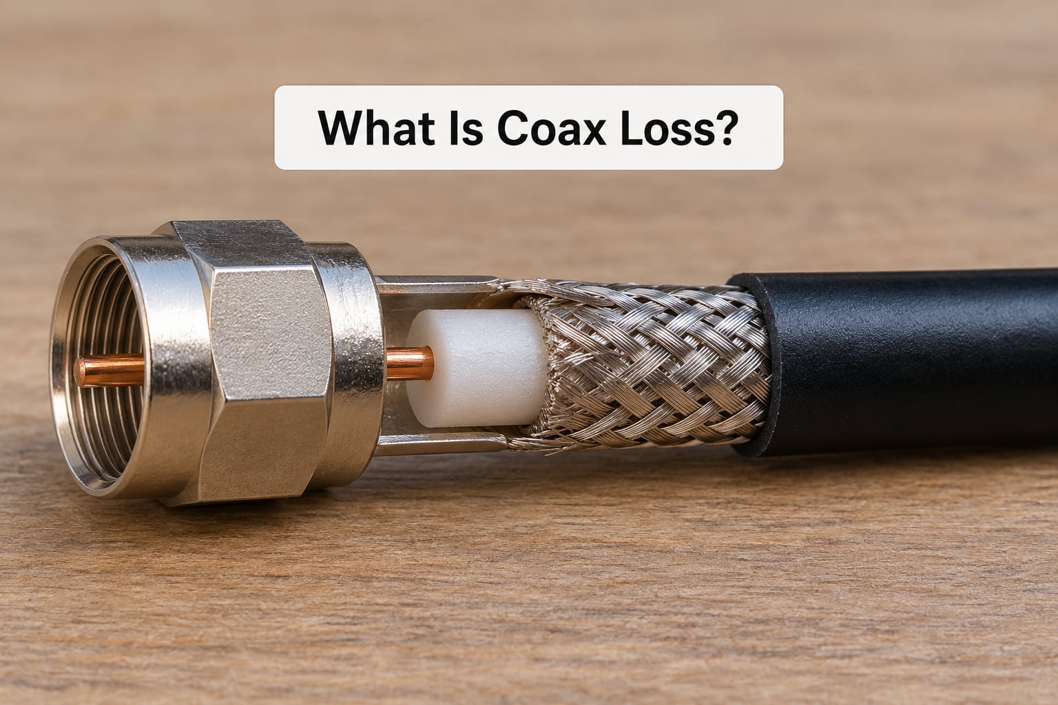
Coax loss, also called attenuation, is the amount of RF energy the cable absorbs and converts to heat as a signal travels along it. It is quoted in decibels per unit length, usually dB per 100 feet, and it is a property of the cable itself rather than of your antenna.
Two useful calibration points anchor everything else. A loss of 3 dB means half the power remains; a loss of 10 dB means one tenth remains. Antenna gain and coax loss also combine the same way, which is why coax loss is often described as negative gain. A 3 dB antenna fed through 3 dB of cable is a 0 dB antenna, no matter how good the aluminium is.
Typical figures for the cables most hams actually run look like this.
| Cable | 14 MHz | 28 MHz | 50 MHz | 144 MHz |
|---|---|---|---|---|
| RG-58 | 4.9 dB/100 ft | 6.3 dB/100 ft | 8.5 dB/100 ft | 12.6 dB/100 ft |
| RG8X | 2.7 dB/100 ft | 3.5 dB/100 ft | 4.6 dB/100 ft | 6.9 dB/100 ft |
| Low-loss 50 ohm (RG-213, LMR-400 class) | 1.5 dB/100 ft | 1.9 dB/100 ft | 2.5 dB/100 ft | 3.7 dB/100 ft |
These are approximate and every manufacturer publishes its own datasheet, so read the number for your actual cable rather than trusting a generic chart. The shape of the table is what matters, and the shape is always the same.
Where coax loss physically comes from
Loss in coaxial cable comes from three places, and a fourth that only shows up when something is wrong.
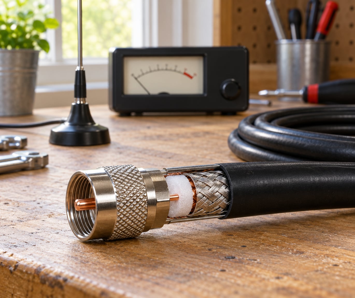
- Skin effect. At RF the current stops flowing down the middle of the centre conductor and crowds into its outer surface. Thicker conductors keep more of that surface, which is why a 50 ohm cable with a thick core loses less than a thin one.
- Dielectric loss. The insulation between the conductors absorbs energy. The figure that describes this is the loss tangent of the material, and low-loss foams are used specifically because their loss tangent is much lower than solid polyethylene.
- Shield leakage. A single braid shield leaves small gaps, and energy radiates out through them. Double-shielded cable with foil plus braid keeps more of the power inside where it belongs.
- Common-mode current. If the shield picks up RF and carries it, the coax itself becomes an antenna. That is not attenuation in the datasheet sense, but it radiates your signal into thin air exactly the same way.
The useful takeaway for anyone who thinks SWR is the only thing that matters: the cable has a fixed loss curve of its own, and the mismatch simply multiplies it.
How Coax Loss Changes the Signal
Why the signal-to-noise ratio stays put on receive
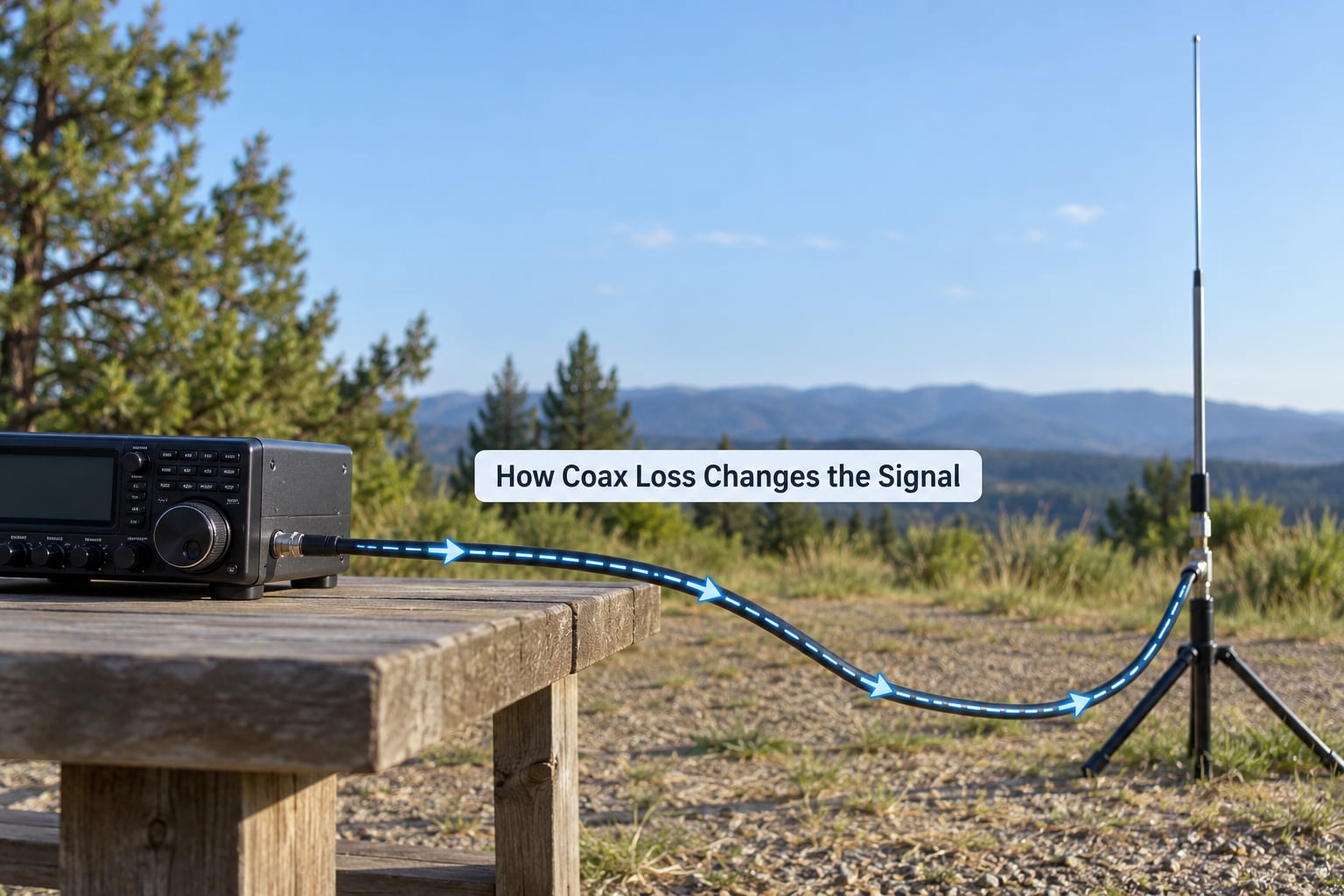
On transmit, coax loss is straightforward and absolute. Whatever the cable absorbs, the antenna never radiates. Run 100 watts into a 100 ft RG8X at 14 MHz and about 2.7 dB goes missing, which leaves roughly 54 watts at the antenna feedpoint instead of 100.
On receive the situation looks different but feels the same. The incoming signal crosses the cable and is attenuated. The atmospheric noise and the local QRM cross the same cable and are attenuated by the same amount, so both arrive weaker and the ratio between them is preserved. A receiver listening through lossy coax has not really heard a weaker station, it has heard the same station at a slightly worse signal level against a noise floor that came down by the same amount.
Where the loss does bite on receive is downstream of that ratio. Digital modes need a usable signal-to-noise margin above the noise floor, and lowering both the signal and the noise by 3 dB moves the whole picture 3 dB down the receiver’s input range. S-meter readings drop, AGC starts compressing earlier, and marginal signals that would have decoded now sit in the noise.
Here is the arithmetic in one line, using the same 100 ft of RG8X at 14 MHz:
| Step | Transmit (100 W out) | Receive (assume 1 unit signal, 1 unit noise) |
|---|---|---|
| At the radio | 100 W | 1.0 signal, 1.0 noise |
| After 2.7 dB of cable | about 54 W | 0.54 signal, 0.54 noise |
| Signal-to-noise ratio | n/a | unchanged, 0 dB in both cases |
Note the asymmetry that trips people up. On transmit, losing 2.7 dB costs you real distance. On receive, the same 2.7 dB leaves your signal-to-noise ratio alone, so the practical penalty is smaller unless you are at the edge of decoding.
Why Cable Type Matters at Different Frequencies
Loss per 100 feet across the common amateur bands, using published figures for each cable type:
| Cable | 7 MHz | 14 MHz | 21 MHz | 28 MHz | 50 MHz | 144 MHz | 440 MHz |
|---|---|---|---|---|---|---|---|
| RG-58 | 3.3 | 4.9 | 5.6 | 6.3 | 8.5 | 12.6 | about 20 |
| RG8X | 1.9 | 2.7 | 3.1 | 3.5 | 4.6 | 6.9 | 9.7 |
| RG-213 | 1.0 | 1.5 | 1.7 | 2.0 | 2.6 | 3.8 | 6.4 |
| LMR-400 | 1.0 | 1.5 | 1.7 | 1.9 | 2.5 | 3.7 | 6.4 |
| LMR-400UX | 0.9 | 1.4 | 1.6 | 1.8 | 2.3 | 3.3 | 5.6 |
| LMR-600 | 0.7 | 1.1 | 1.2 | 1.3 | 1.6 | 2.4 | 4.0 |
All values are dB per 100 feet. The pattern across every row is that loss climbs steeply with frequency, roughly with the square root of it, because both the conductor and the dielectric get worse at higher frequencies.
Construction details that matter
Centre conductor size is the biggest single lever. Going from RG-58 to RG8X thickens the conductor, and going again to LMR-400 thickens it further. That is why the 440 MHz column is where the differences turn into numbers you can hear: 9.7 dB per 100 ft for RG8X against 4.0 dB for LMR-600 is the difference between a usable feedline and a very expensive heating element.
The dielectric is the second lever. Solid polyethylene is cheap, robust and lossy. Foam and gas-filled construction cut dielectric loss, and that is the main reason RG8X beats RG-58 by about 2 dB at 14 MHz rather than by a little.
The shield matters for interference rather than for your signal budget. A single braid has coverage gaps that can let noise in and your signal out. Foil plus braid is better, and a good double-shielded cable also holds its impedance better when it is bent or stapled along a wall.
Check the impedance too. Conventional amateur antennas want 50 ohm coax. RG-6 is 75 ohm and is a common accidental choice when someone grabs whatever is on the reel.
Finally, watch out for two things that datasheets cannot protect you from. Poorly crimped or soldered connectors can add several tenths of a dB each, and no-name cable sold as LMR is frequently not LMR at all. Cheap lookalike cable can measure well above its claimed loss, which is why it is worth buying from a seller who will tell you the centre conductor diameter.
How Impedance Mismatch Makes Coax Loss Matter More
A well-matched antenna sends its power straight down the cable. A mismatched one sends some of it back, and that reflected wave has to travel the whole length of the feedline a second time, getting absorbed on the way in. So a mismatch does not add a fixed penalty, it multiplies the cable’s own loss by roughly one plus the size of the reflection.
Here is what that does to a 2.7 dB run, which is 100 ft of RG8X at 14 MHz:
| VSWR | Reflection size | One-way loss | Power remaining at the antenna from 100 W |
|---|---|---|---|
| 1:1 | 0 | 2.70 dB | 54 W |
| 1.5:1 | 0.20 | 3.24 dB | 47 W |
| 2:1 | 0.33 | 3.60 dB | 44 W |
| 3:1 | 0.50 | 4.05 dB | 39 W |
| 4:1 | 0.60 | 4.32 dB | 37 W |
Look at the last two columns together. Going from a perfect match to 3:1 costs about 1.35 dB, which is 15 watts out of 100. That is a real cost, and it is also smaller than most people imagine. What usually hurts far more is a high SWR on thin coax, because the multiplier lands on a loss figure that is already large.
Two further points on mismatch. First, a lossy cable cannot rescue a bad match, and no cable will. If the antenna system is badly wrong, better feedline moves the SWR reading a fraction of a dB and changes very little else. Fix the match or the antenna first.
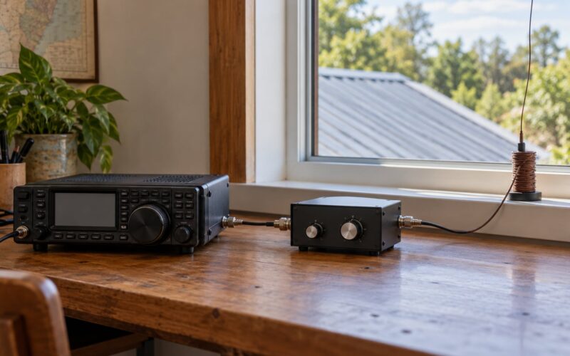
Second, an antenna tuner does not restore power the cable has already dissipated. A tuner matches the transmitter output impedance to whatever the antenna is presenting, and the power still has to cross the coax to get there. If the cable is soaking up 3 dB, the tuner matched around it. Some tuners also add their own insertion loss, typically a fraction of a dB for a decent one and noticeably more for a lossy arrangement or a long coax run.
Where the SWR myths come from
SWR does not eat your power. Reflected power is not gone, because the transmitter reabsorbs most of it. The two real costs of a high SWR are the multiplied feedline loss we just calculated and transmitter foldback, where the radio deliberately reduces its own output to protect itself.
Foldback is a different mechanism entirely, and separating the two matters when you are chasing a problem. A radio that drops from 100 watts to 20 watts on one band is not losing power in the coax, it is protecting its finals. No amount of feedline will change that, and changing the feedline while ignoring it wastes a weekend.
There is also a power-handling angle. High VSWR puts voltage peaks on the cable at the points where the standing wave is highest, and thin or cheap coax has less margin for that. Running a thousand watts of FM into 3:1 on RG-58 is asking for trouble in the cable, not just the antenna.
How to Calculate the Loss in Your Feed Line
The calculation is two steps. Take the manufacturer’s dB per 100 feet figure at your highest operating frequency, multiply it by your run length in hundreds of feet, then add the mismatch multiplier from the table above.
Formula one, matched loss: total dB = (dB per 100 ft ÷ 100) × length in feet
Formula two, with mismatch: actual dB = matched dB × (1 + reflection)
Worked examples, all at 14 MHz where RG8X is 2.7 dB per 100 ft:
| Run | Cable | Matched loss | Power remaining from 100 W |
|---|---|---|---|
| 25 ft | RG8X | 0.68 dB | 86 W |
| 50 ft | RG8X | 1.35 dB | 73 W |
| 50 ft | LMR-400 | 0.75 dB | 84 W |
| 100 ft | RG8X | 2.70 dB | 54 W |
| 100 ft | RG-213 | 1.50 dB | 71 W |
| 200 ft | RG8X | 5.40 dB | 29 W |
| 200 ft | LMR-400 | 3.00 dB | 50 W |
The 200 ft RG8X row is the one that changes minds. Running a hundred watts and reaching the antenna with 29 watts is worse than most operators expect, and moving to LMR-400 recovers about 21 watts, which is about 3 dB and does add up on the air.
Push that further and the numbers stop being funny. 200 ft of RG-58 at 14 MHz is about 9.8 dB, so only a tenth of the power from the radio is still there at the antenna and nine tenths is heat in the jacket. Any real station that runs a long feedline and still copies the band is working with much less signal than the radio’s display implies.
Fill this in for your own station and the arguments stop:
| Line item | Your figure |
|---|---|
| Cable type | |
| Run length in feet | |
| Highest frequency you use | |
| Matched loss from the datasheet | |
| Matched loss for your run | |
| VSWR on that band | |
| Mismatch multiplier | |
| Actual total feedline loss | |
| Power reaching the antenna | |
| Tuner or unun insertion loss | |
| Connector losses |
Add the last two lines to the total. A matching network, a couple of connector pairs and the cable together tell you what your station is really putting out, which is usually a different number from what the radio’s display claims.
What Coax Loss Means for Receiving
How coax loss affects antenna performance during weak-signal reception
Five separate things determine what you copy: antenna gain, receiver sensitivity, atmospheric noise, local interference, and the feedline. Only the last one is on this page, and it is usually the smallest of the five on a receive-only setup.
Take a quiet 40 metre night. The band noise floor is set by the sky, not by your station, so the cable attenuates a signal and a very weak background equally, and the ratio holds. The loss that matters is the fraction of your receiver’s total system noise figure that arrives through the cable, and a healthy receive antenna pushes a great deal of signal down the line compared to a lossy one.
That is why a quiet receiving setup benefits from good cable while a noisy one does not. On a band with heavy local interference, the interference is often entering the receiver through the same antenna and cable, so the loss just scales everything and changes nothing you can hear. On a quiet band, the signal you are trying to copy is the only thing arriving, and every decibel the cable takes is a decibel that never reaches the front end.
Shortening the cable helps, and it is the cheapest receiver improvement available to most people. Moving the antenna closer, or putting the receiver at the masthead with a short run, cuts the cable loss to near zero.
The exception is a strong local signal. Twenty feet of RG-58 on a local FM repeater costs you about 1 dB and nobody hears the difference. A long run matters for weak signals, not loud ones, and anyone who tells you their receiving range collapsed because of the cable is usually hearing interference, not the cable.
What Coax Loss Means for Transmitting
On transmit the loss is a straight subtraction from your output, and it is the side people can actually measure. Same 100 watts, same antenna, three different runs at 21 MHz:
| Run and cable | Loss at 21 MHz | Power at the antenna | Percentage lost |
|---|---|---|---|
| 100 ft LMR-400 | 1.7 dB | 68 W | 32% |
| 100 ft RG8X | 3.1 dB | 49 W | 51% |
| 100 ft RG-58 | 5.6 dB | 28 W | 72% |
| 50 ft RG8X | 1.55 dB | 70 W | 30% |
Those percentages are where the forum panic comes from, and the dB behind them is less dramatic than the percentage makes it sound. Sending 28 watts instead of 100 is 5.6 dB, which is a shorter reach but not a broken station. QRP operators feel this hardest, because 5 watts through 100 ft of RG8X at 21 MHz leaves about 2.5 watts at the antenna.
High-power stations have the opposite problem in reverse. At 1,000 watts, 3 dB of cable burns off more than you would ever lose to a slightly marginal antenna, so the same run should use better cable even though the percentage sounds the same.
Absorbed power and reflected power are worth keeping separate. Cable loss is absorbed power, it leaves the system as heat, and no antenna or tuner can recover it. Reflected power goes back down the cable to the transmitter, where most of it is reabsorbed. Neither one shows up in a low SWR reading, which is why a radio can read a beautiful 1.2:1 and still be running at half power by the time the signal reaches the antenna.
How to Choose the Right Coax for Your Antenna
Work through these in order and the cable picks itself.
- Your highest frequency. The loss you care about is the loss at the top of your range, not the band you happen to like. 10 metres users need a different cable from 80 metre users, and often the same radio.
- Your run length. Under 50 feet, almost any 50 ohm coax is fine. Past 100 feet, the cable becomes the deciding factor in the whole system.
- Your power. Low power relaxes the voltage and heating limits, so thin cable is more usable. High power on a mismatch is where cheap coax fails.
- Where it lives. Permanently outdoors, buried or on a mast, buys the better UV and moisture-rated cable. A coil in the back of a car for POTA does not need it, and for short portable runs the difference in cable usually matters far less than people expect.
- Weight and handling. A 100 ft run of LMR-600 is heavy and awkward for a portable setup, and a heavy cable sags, bends and eventually cracks at the connectors.
When RG-58 is genuinely fine
Under about 30 feet on the low bands at modest power, RG-58 is a reasonable choice, and plenty of stations have no reason to change it. A receive-only longwire at 10 feet of RG-58 loses less than a decibel. The forum consensus on RG8X is roughly that it is not the finest cable but it is not a problem on a short run.
Apply the sub-1 dB rule. Work out the difference between your current cable and the one you are tempted to buy. If it is under 1 dB, buy it if you like the cable, but do not expect to hear a difference. If it is 2 dB or more, the upgrade or the shorter run is worth doing. If it is 3 dB or more, the problem is your run length and no cable will fix it properly.
Practical Ways to Reduce Coax Loss
In the order I would actually try them.
- Shorten the run. Every foot you remove is a foot of loss you never had. The best coax is the length you never buy.
- Match the cable to your top frequency. Choose the dB rating for the band you will actually work, not the band you will probably work one day.
- Improve the match. A better antenna or a properly set up tuner cuts the multiplier in the mismatch table. This costs nothing if the antenna was the wrong shape or the wrong height all along.
- Cut the splices. Every barrel connector, every adapter and every inline lightning arrestor is another place to lose a few tenths. Buy one good length.
- Make the connectors properly. A well-made N-type or a correctly fitted SO-239 is close to nothing. A badly crimped PL-259 on RG-58 can cost more than a foot of good cable.
- Keep water out. Water getting in at the connectors is the number one way coax gets ruined, and it shows up as an unexplained SWR climb after rain rather than as a failed continuity test. Self-amalgamating tape and strain relief at both ends cost almost nothing.
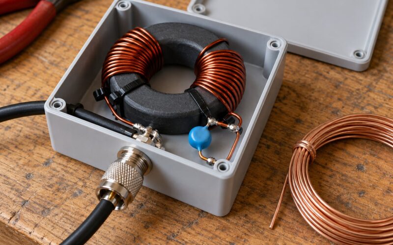
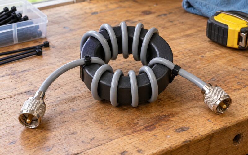
- Stop the coax radiating. If the shield is carrying current, your feedline is an antenna and your loss figures mean nothing. Common-mode chokes at the radio end, and a proper braid bonding, fix most of this.
How to Test an Installed Feed Line
The reliable method is substitution, and it is cheaper than most people expect. Run your transceiver through a short length of known-good cable into the same antenna, and compare the reported power or S-meter reading with the same setup through your installed run. Same power setting, same band, same antenna, different cable. A clean 3 dB drop means the installed cable really is absorbing 3 dB, whatever the type name on the jacket says.
Test at your highest intended frequency, because that is where the loss is worst and where the answer matters most. Repeat at your lowest if you can, since cable that looks fine on 20 metres can be marginal on 2 metres.
A low-noise antenna analyser is convenient for checking SWR at the antenna end, but it is not a reliable way to measure absolute cable loss. Its measurements repeat well and compare well, and an absolute figure that looks suspicious usually reflects the analyser or the reference load rather than the cable. Treat the numbers as a comparison, not a certificate.
A vector network analyser is the instrument that will actually settle it, and if you do not have access to one, the substitution test above is the next best thing. Whatever method you use, compare the result against the manufacturer datasheet rather than against your memory of what the cable used to be.
One last check worth doing: watch the SWR while you flex the installed cable and wiggle the connectors. A reading that moves means a bad joint, water in the cable or a connector that has backed off, and none of those are fixable by buying better cable.
Frequently Asked Questions
Does coax loss change the antenna’s radiation pattern?
No. The feedline sits between the radio and the antenna, and the pattern is set by the antenna, its height and its surroundings. What changes is the power available to radiate, so a lossy feedline lowers the signal level across the whole pattern equally. The one exception is common-mode current on the coax, where the shield radiates and distorts the pattern, and that is a fault rather than a normal effect of cable loss.
Does low-loss coax improve the receive range of a shortwave radio?
Only a little, and less than most people expect. The cable attenuates the incoming signal and the noise floor by the same amount, so the signal-to-noise ratio is preserved. On a quiet band with a weak signal, the loss lowers both below what your receiver can use and weak signals may stop decoding. On a band full of local interference, the loss just scales everything and you will hear no difference at all.
Can an antenna tuner eliminate coax loss?
No. A tuner matches the transmitter to whatever impedance the antenna presents, but the power still has to cross the feedline to get there, and whatever the cable absorbs stays absorbed. A tuner can reduce the mismatch multiplier on your feedline loss, which helps, and it can add its own insertion loss. It will not recover the 3 dB a 100 ft run of RG8X uses up on 14 MHz.
How much coax loss is acceptable for amateur radio?
Under 1 dB total is effectively free, 2 dB is noticeable on a good signal, and 3 dB or more is worth fixing. The difference between a 1 dB and a 2 dB system is small in practice, so an expensive cable upgrade on a short run buys you very little. The sub-1 dB rule is a good guide: if the improvement is under 1 dB, do not expect to hear it.
Should I use lower-loss coax or move the antenna closer to the station?
Move the antenna closer, every time. Shortening the run from 200 ft to 50 ft typically saves 4 dB or more, and it also cuts noise pickup and connector count. If you cannot shorten the run, put the radio at the antenna end with a short feedline. Buy lower-loss coax when the run is already short and you still have a mismatch to absorb.
Conclusion
Start at the top of your range. Find your cable’s dB per 100 feet at that frequency, multiply by the run length, then add the mismatch multiplier from your actual SWR reading. That number is your real feedline loss, and it is usually larger than the operator’s intuition says.
Then fix the big items in order. Shorten the run if you can, because no cable beats no cable. Match the antenna properly, and check that the coax is not carrying current on the shield. Then buy better cable, and you will know how many dB it returns before you spend the money.