SWR stands for standing wave ratio: the ratio of the maximum to the minimum RF voltage measured along the feedline between your transmitter and your antenna. A reading of 1:1 means the antenna impedance matches the 50 ohm coax and nothing comes back. A reading of 4:1 means roughly 36 percent of your forward power is reflected toward the radio instead of going out the antenna.
That is what SWR really means for your transmitter: a mismatch meter for one system, not a score for your antenna. New operators often fear a high reading will destroy an expensive radio. It usually will not, and the section on damage below explains the mechanism and the real thresholds.
Table of Contents
- 1What SWR Really Means for Your Transmitter
- 2Why 50 Ohms?
- 3SWR vs VSWR vs return loss
- 4SWR Numbers at a Glance
- 5How Is SWR Measured?
- 6What SWR Number Is Acceptable?
- 7Why Does a High SWR Matter?
- 8What Can Change Your SWR Reading?
- 9How to Check Your Antenna System
- 10How to Improve High SWR
- 11SWR for Portable Antennas and Common Bands
- 12Frequently Asked Questions
- 13Is 1.5:1 SWR better than 1:1?
- 14Is an SWR of 2:1 acceptable?
- 15Does an antenna tuner change the antenna’s actual SWR?
- 16Why does my SWR reading change between bands?
- 17Is 3:1 SWR dangerous for my transmitter?
- 18Does low SWR automatically mean the antenna works well?
- 19Conclusion: Start With the Reading, Not a Magical Number
What SWR Really Means for Your Transmitter
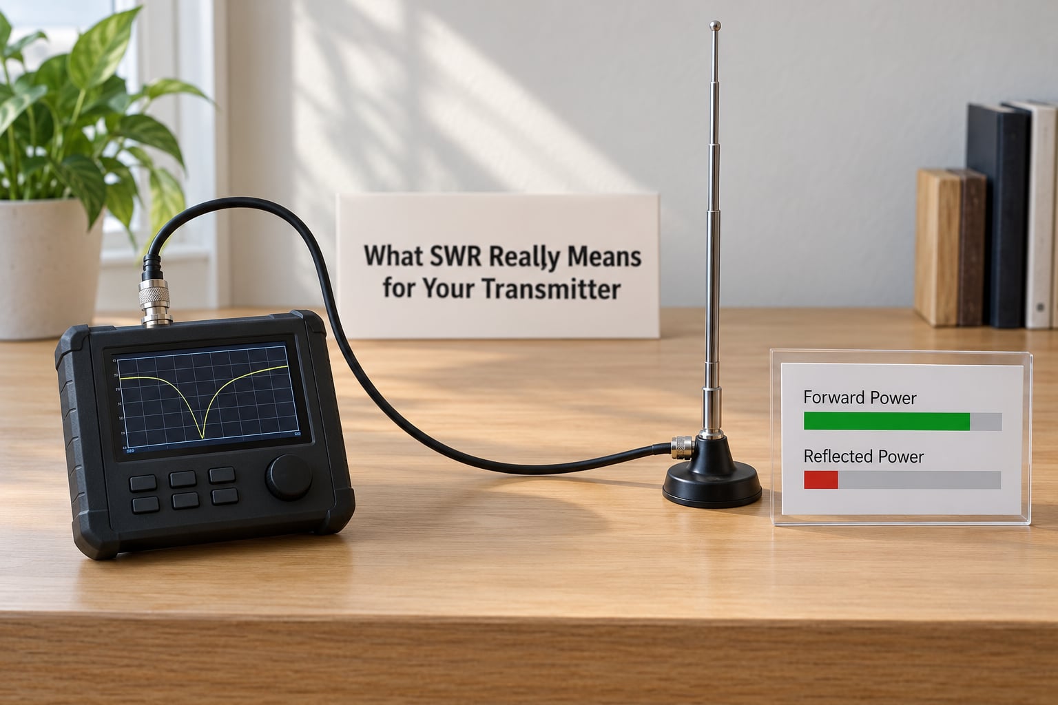
Your transmitter pushes RF power down the coax. At the antenna end, the wave meets an impedance that is almost never exactly 50 ohms. A half-wave dipole cut for the band presents roughly 72 ohms at resonance, and a quarter-wave vertical over a large ground plane sits closer to 36 ohms. Both are fine antennas. Neither is a 50 ohm load.
Wherever the antenna impedance differs from the coax’s characteristic impedance, part of the wave turns around and travels back toward the radio. The outgoing and returning waves add and subtract along the line, producing voltage maxima and minima: the standing wave. The bigger the mismatch, the deeper the dips.
Two properties of an antenna drive that mismatch. Impedance is made of resistance, which is what you want, and reactance, which is the unwanted inductive or capacitive leftover. An antenna cut slightly too short is reactively capacitive at the operating frequency. Cut too long, it is inductive. The dip in SWR you see on the meter is reactance moving through zero.
Reflected power is also not simply lost. It travels back down the line, is absorbed by the transmitter’s output network, and re-enters the antenna on the next cycle. At a modest mismatch most of that energy still gets radiated eventually, which is why a 2:1 reading is not the disaster that forums sometimes suggest.
Why 50 Ohms?
Fifty ohms is not a law of physics. It is an engineering compromise adopted because it allows high power handling in a reasonably small cable, and because a dipole and a quarter-wave vertical can be made to work well with simple matching parts. Nearly all amateur transceivers, wattmeters and SWR meters are calibrated to 50 ohms, which is why the meter reports a ratio against that reference.
A 72 ohm dipole into 50 ohm coax still radiates efficiently. You simply cannot get a 1:1 reading without a matching network, and no part of the radio cares about the number you see on screen as long as the transmitter is protected.
SWR vs VSWR vs return loss
Three terms describe the same mismatch in different units. Amateur operators say SWR; engineers write VSWR because voltage is what the formula uses. Return loss states the same thing in decibels, higher being better.
| Term | What it measures | Direction |
|---|---|---|
| SWR | Maximum to minimum voltage ratio on the feedline | Lower is better, 1.0 to infinity |
| VSWR | Same quantity, engineering notation | Lower is better |
| Return loss | How much of the wave came back, in decibels | Higher is better, measured upward |
At 1.5:1 the return loss is about 14 dB. At 2:1 it is roughly 9.5 dB, and at 3:1 about 6 dB. If you read specs on a commercial antenna or a commercial broadcast system, this is the column they quote, and the numbers map directly onto the meter reading you see on the bench.
SWR Numbers at a Glance
The table below is the ladder most operators carry in their head. Reflected power is calculated from the reflection coefficient, where the ratio of (SWR minus 1) to (SWR plus 1) squared gives the fraction of forward power returning.
| Reading | Reflected power | What it means in practice | Likely cause |
|---|---|---|---|
| 1.0:1 | 0 percent | Perfect match to 50 ohms at that one frequency | Analyzer into a tuned load or a dummy load |
| 1.1:1 | About 0.2 percent | Excellent; nothing to fix | Normal for a well-tuned Yagi or beam |
| 1.5:1 | About 4 percent | Excellent on any band and any power | Resonant dipole or vertical with good mounting |
| 1.8:1 | About 8 percent | Excellent; still comfortable operating margin | Normal on the edge of a narrow-band antenna |
| 2.0:1 | About 11 percent | Usable in most setups, worth fixing at high power | Coax length, mounting height, nearby objects |
| 2.5:1 | About 18 percent | Workable but the coax starts running warmer | Antenna too short, poor ground plane, damaged feedline |
| 3.0:1 | 25 percent | Poor; transceivers with protection will complain | Antenna off band, bad connector, broken coax |
| 4.0:1 | 36 percent | Troubleshoot before running power | Near-open or near-short circuit |
| Infinite | 100 percent | Nothing is radiating or receiving | Open coax, disconnected antenna, broken whip |
One caution on the 1.0:1 row. A perfect dummy load reads 1.0:1 and radiates nothing at all. That is the sharpest rebuttal to treating SWR as an antenna quality score, and it comes up repeatedly on the myGMRS forum, where operators post nearly identical readings of 1.01 to 1.56 across GMRS, marine, VHF, UHF and MURS on four different radios and still ask whether the antenna is any good.
How Is SWR Measured?
An SWR meter sits in the feedline and samples the forward wave, then the reflected wave. You switch to FWD, key the transmitter at a fixed low power, note the reading, switch to REF, key again, and compute the ratio with a chart or a calculator built into the meter. Forward and reflected power, not voltage, are what the coupler detects, which is why a wattmeter-style instrument gives a more repeatable number than an inline meter with a moving pointer.
The formula behind it is simple. With forward power as F and reflected power as R, the reflection coefficient is the square root of R divided by F, and SWR is (1 plus that coefficient) divided by (1 minus it). At F equals 100 watts and R equals 11 watts, the coefficient works out to about one third and the SWR lands at 2.0:1.
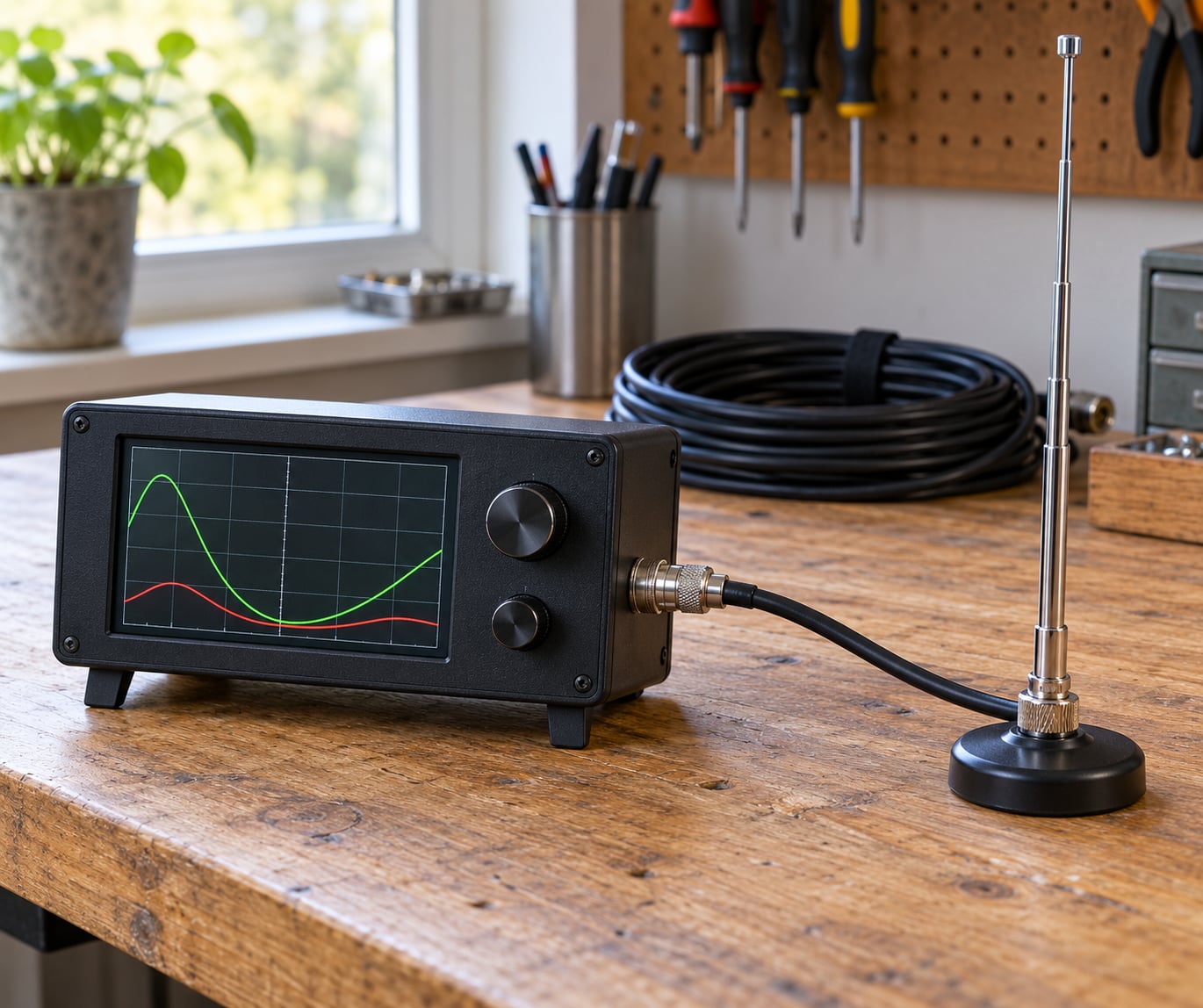
An antenna analyzer does something different. It sweeps a range of frequencies and displays the antenna’s impedance, reactance and minimum SWR, which tells you the resonant frequency and how sharp the antenna is. For troubleshooting a mismatched antenna an analyzer is far more informative than a wattmeter, because it shows you which way to move the resonance.
| Instrument | Shows you | Best for |
|---|---|---|
| SWR meter or wattmeter | Forward and reflected power at one frequency | Checking a finished installation |
| Transceiver readout | Averaged SWR estimate, usually coarse | Quick confirmation while operating |
| Antenna analyzer | Impedance, reactance, resonance, minimum SWR | Finding out what the antenna is really doing |
| Dummy load | Always close to 1:1, radiates nothing | Bench testing a radio safely |
Every one of those instruments assumes a 50 ohm system. A reading from a load of some other impedance is only meaningful as a ratio against that reference.
What SWR Number Is Acceptable?
There is no single universal threshold, and any article that gives you one is selling you a target. What matters is your transmitter’s power, its protection circuitry, the loss in your feedline and how much bandwidth the antenna needs to cover.
Most operators treat 1.5:1 to 2.0:1 as the practical working range, and that is reasonable. A 5 watt handheld with a factory antenna will happily run at 2.5:1 all day without complaint, because the RF power is trivial and modern sets fold back or alarm rather than cook themselves. A 100 watt HF transceiver running into a 2:1 mismatch still runs fine on most designs, though you are giving away margin on a bad day. A legal-limit amplifier with no built-in protection is the case where a reading above 2:1 deserves real attention, because that is where peak voltage and current on the final amplifier devices climb.
Band coverage changes the picture. A 40 meter dipole cut for 7.074 MHz will read very close to 1:1 in the phone portion of the band and climb past 3:1 above 8 MHz, because it simply is not an antenna up there. Expect a narrow-band antenna to wander across a band, and judge the band edges rather than one frequency.
The other half of the answer is loss. Coax loss rises with frequency, so a feedline that is nearly transparent at 7 MHz may cost real watts and add to your measured reading at 14 MHz or 450 MHz. On VHF and UHF, where good cable costs several tenths of a decibel per foot, a long run can turn an antenna that radiates well into a system that reads badly.
Why Does a High SWR Matter?
Sort the claims into two piles. These are false, or at least badly overstated.
- High SWR always blows up your radio. No. Most modern transceivers detect excessive reflected power and reduce output or shut down.
- A perfect 1:1 reading means your signal goes out stronger. Not necessarily. A dummy load reads 1:1 and radiates zero.
- An antenna tuner fixes the antenna. It changes the impedance the transmitter sees, not what the antenna is.
- SWR matters when you are only receiving. It barely does. A mismatch of this kind has almost no effect on receive sensitivity.
These are true, and they are the actual reasons to care.
- Voltage and current peaks on the feedline and inside the output stage rise with the standing wave. That is what stresses the final amplifier, and it is why high-power amplifiers are the ones with protection circuits.
- Lossy or badly matched coax runs warmer. The outer shield can carry significant current at high VSWR, and a coax that leaks current radiates from the feedline itself, which distorts your pattern and couples into nearby equipment.
- Output power falls. The transmitter delivers less forward power for the same drive, so your signal genuinely is weaker.
- Modern radios will complain. Overload protection, SWR alarms and auto-tuners exist because high mismatch is a real condition worth flagging rather than ignoring.
An antenna tuner deserves its own paragraph because the misconception is so widespread. A tuner is a variable low-pass and high-pass network with a capacitor and inductor that the radio drives to transform whatever impedance it sees into 50 ohms. It does nothing to the antenna. Read the SWR at the antenna with a tuner in the line and you will get the same number you got before, because the reflection happens at the antenna regardless.
Most of the alarmist writing you will find dates from transmitters with no protection at all, and it still circulates in 2026. The mechanism has not changed, but your radio almost certainly measures its own mismatch and reacts to it.
What Can Change Your SWR Reading?
If the same antenna can read two different values, the difference is in the environment or the measurement, not in the antenna’s design.
Height and surroundings. An antenna that reads 1.4:1 on the ground can read 2.5:1 ten feet up next to a chimney. Metal roofs, gutters, fences and vehicles all couple into the near field and disturb the pattern.
Frequency. Resonance is a narrow phenomenon. Move a few percent of frequency and the reading can move a lot.
Feedline length. Coax is a transmission line, and the input impedance at the radio end is transformed by the cable’s length. An arbitrary length can show you a high reading at the radio when the antenna is close to 50 ohms, and a multiple of a quarter wavelength can make the reverse happen. This is why swapping to a different cable length sometimes “fixes” a number that never needed fixing.
Connectors. A loose, corroded or badly fitted PL-259 on a PL-259-to-SO-239 adapter is one of the most common causes of a permanently high reading.
Weather and age. Moisture in the coax, UV-cracked jacket, a chewed cable behind a desk, or a lightning strike through a protector all shift the reading.
Output power. Built-in readouts are usually averages sampled from the forward and reflected detectors, and they vary with drive. A transceiver transmitting at 5 watts may report a different figure than the same radio at 100 watts.
How to Check Your Antenna System
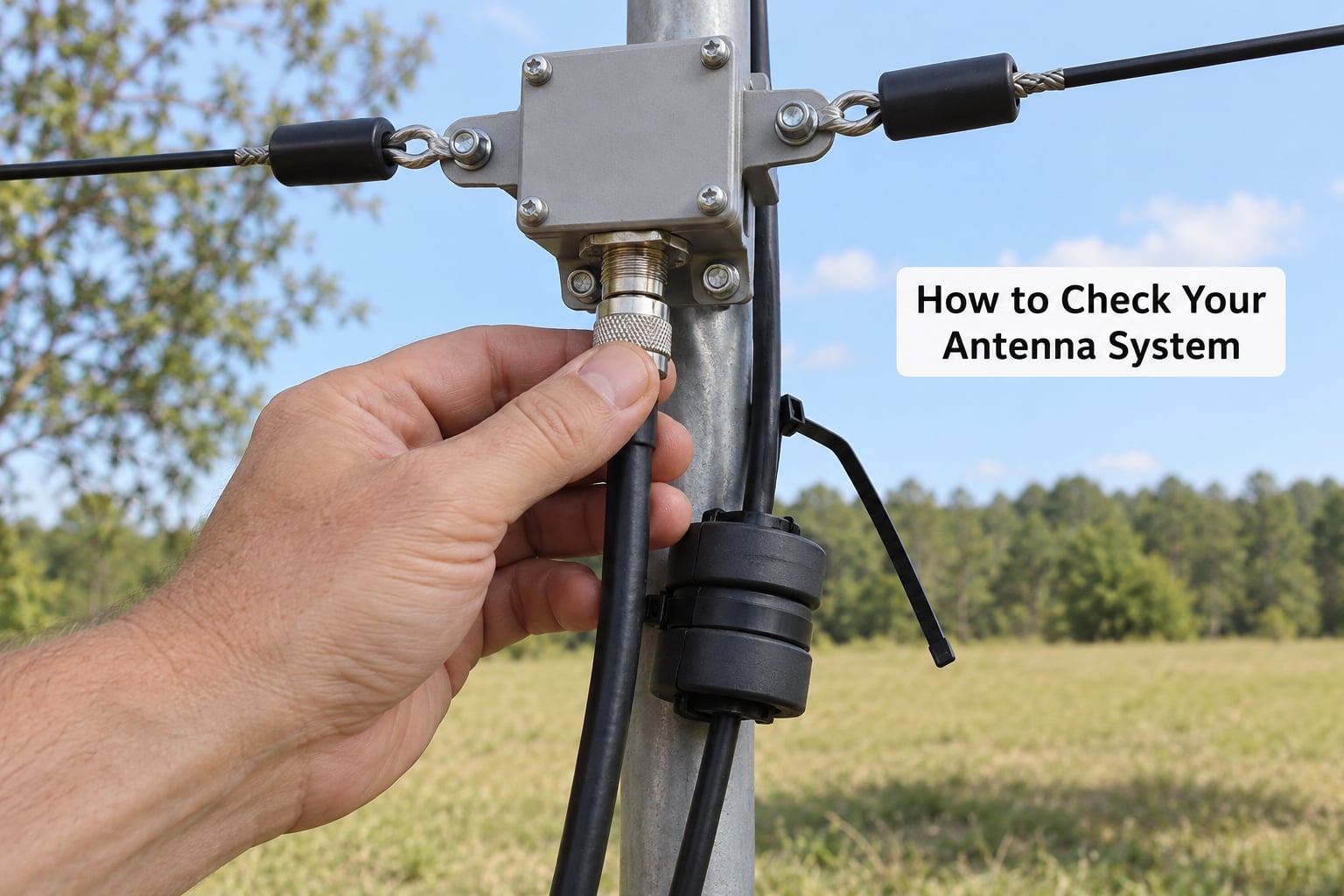
Check everything at low power first. Five watts into an unknown feedline costs nothing and tells you almost as much as a hundred.
- Start with a visual inspection. Look for crushed, kinked, chewed or weathered coax, and for connectors finger-loose or green with corrosion.
- Substitute a known load. Put a 50 ohm dummy load or a resistive termination where the antenna goes. If the reading stays high with a known good load on the end, the fault is in the radio, the meter or the feedline, not the antenna.
- Measure the coax. With the antenna disconnected, check continuity from the centre conductor to the shield at both ends, then check centre to centre and shield to shield for a clean path. Anything that reads open or short means new cable.
- Try a short known-good jumper. A metre or two of known-good coax between the radio and the antenna is a fast way to separate feedline trouble from antenna trouble.
- Measure at the antenna end. Connect the meter directly at the antenna feed point. If the reading at the radio is high but the reading at the antenna is low, you have a feedline problem.
- Recheck away from the bench. Close doors, car hoods and garage doors change readings. Repeat the check in the real installation position before believing a number.
| Symptom | Likely cause | Corrective action |
|---|---|---|
| Reading is higher on the low channel than the high channel | Antenna is electrically too short | Lengthen it; add turns or a loading coil |
| Reading is higher on the high channel | Antenna is electrically too long | Shorten it; never transmit into a retractable whip while adjusting it |
| Reading was fine, now reads high after moving it | Nearby metal, roof or vehicle coupling | Change height or location |
| Reading jumped after a storm | Moisture ingress or a damaged protector | Inspect connectors, replace the cable run |
| Reading fine on the bench, high in place | Different surroundings, doors and hoods closed | Re-measure in the operating position |
| Infinite reading | Open coax or disconnected antenna | Trace the feedline end to end |
| Reading changes with RF power | Coarse built-in averaging | Confirm with a dedicated wattmeter |
That short-versus-long rule is worth memorizing, because it tells you which direction to turn. Higher at the low end of the band means the antenna is too short and you add length. Higher at the high end means it is too long and you remove it.
How to Improve High SWR
Work through these in order, cheapest and most likely first.
- Move the antenna. Height and clearance change more than any coax swap ever will. Try a different mast location before touching anything else.
- Move the metal. Relocate the ground connection, get the whip away from a roof edge or a car body, and clear away stored items near a portable setup.
- Change length or design. Trim or extend a whip by small increments and remeasure. If a narrow-band antenna will not cover the band, the right fix is a different antenna, not a tuner.
- Replace the cable run. If you cannot get the connector tight with fingers and a proper wrench, or the cable has been crushed, replace it. Do not splice and do not tape.
- Use a better feedline. Shorter runs of lower-loss coax often improve both the reading and the actual signal, especially above 50 MHz.
- Tune at the radio last. An automatic or manual tuner will flatten the meter to 1:1 on many antennas, and it is a legitimate tool when you understand what it is doing. Understand its power limit and its bandwidth, and never transmit through a tuner that is not rated for the band.
The order matters. Putting a tuner on a bad installation hides a problem you will still have after the tuner gives up, and it adds a component that can fail at full power.
SWR for Portable Antennas and Common Bands
Portable setups are where high readings are most common and most benign. A telescoping whip is usually a single quarter-wave element with no ground system, so its impedance floats with whatever is under it and it rarely reaches 50 ohms anywhere. Readings of 2:1 to 3:1 on a handheld or a field radio are ordinary and work fine at the 5 to 10 watts those radios produce.
Factory rubber duck antennas are the extreme case. A short stub on a handheld will often read 3:1 or worse, yet the radio works, because the mismatch is modest and the power is tiny. Changing the antenna changes the reading without much changing the signal.
On HF, a resonant dipole hung from a tree or a wire strung to a fence will sit close to 1:1 where it is cut, and climb quickly away from that frequency. Cut for the lower part of the band you want and you will have a comfortable reading across more of it.
On VHF and UHF, a 4:1 reading on a handheld at a repeater site usually means the antenna is the wrong length, the coax has a bad connector, or the radio is sitting next to a metal surface. The one thing never to do is adjust a retractable whip while transmitting, on any band.
Frequently Asked Questions
Is 1.5:1 SWR better than 1:1?
Slightly, and it does not matter. A 1.5:1 reading reflects about 4 percent of forward power returning to the radio. At 100 watts that is roughly 4 watts of reflected power, which modern output stages handle without complaint. Most operators treat anything under 2:1 as an excellent working match. Chasing 1:1 on an antenna that is designed to present 72 ohms can cost you an afternoon and gain you nothing on the air.
Is an SWR of 2:1 acceptable?
Yes, in nearly every amateur setup. Two to one means about 11 percent of forward power is reflected, and the transmitter still delivers close to its rated output. A 100 watt HF rig will run indefinitely at 2:1 on a design with proper output protection. Pay closer attention above 2:1 on a legal-limit amplifier without built-in protection, and on VHF or UHF where feedline loss adds to the problem.
Does an antenna tuner change the antenna’s actual SWR?
No. The tuner sits at the radio end and transforms whatever impedance the feedline presents into 50 ohms, so the meter behind it reads a low number. Measure at the antenna end instead and the reading is unchanged. A tuner is useful when you need to match a mismatched antenna on several bands, and it is limited by its own power handling and its usable bandwidth. It never improves radiation efficiency.
Why does my SWR reading change between bands?
Because an antenna is resonant over a narrow range of frequencies, and moving outside that range changes its impedance quickly. A dipole cut for 7 MHz will read close to 1:1 in the lower phone segment and climb past 3:1 at 10 MHz, where it is simply too short to be an antenna. The same effect shows up within one band on narrow-band antennas, so measure at the band edges rather than at one spot in the middle.
Is 3:1 SWR dangerous for my transmitter?
For a handheld or a 100 watt transceiver, no. At 3:1 about a quarter of your forward power returns, and both the feedline and the final amplifier see higher peaks, but built-in protection on modern sets will alarm or reduce output. Below roughly 3:1 there is usually nothing to worry about at amateur power levels. Above it, fix the installation rather than relying on the radio to survive it, and treat a legal-limit amplifier as a different case entirely.
Does low SWR automatically mean the antenna works well?
It does not. A perfect dummy load reads 1.0:1 and radiates nothing whatsoever, which proves the point neatly. SWR tells you only how closely the impedance at the feed point matches 50 ohms at one frequency. Bandwidth, efficiency, radiation pattern and noise figure determine how well the antenna actually works, and none of those appear in the SWR number.
Conclusion: Start With the Reading, Not a Magical Number
SWR is a mismatch measurement across the feed point, the coax and the radio. Below about 2:1 on amateur power it is a comfort indicator, not a safety limit, and a reading on its own tells you nothing about how well your antenna radiates.
So start practical: verify the installation at low power, substitute a known load if you want to isolate the fault, and remember that a higher reading on the low channel means your antenna is too short while a higher reading on the high channel means it is too long. Move the antenna and the metal around it before you touch the coax or reach for a tuner. When you do judge the result, judge it on bandwidth, loss and actual field performance rather than on a single number on a meter.