A stealth HF antenna is simply an HF wire or loop antenna installed so that nobody can see it from the street or a neighboring property, usually thin wire run through a hedge, along a fence line, under roof eaves or through a rain gutter. Learning how to build a stealth HF antenna for a small yard comes down to three things: a wire length matched to your bands, a feedpoint that is electrically sound, and a ground or counterpoise that actually works.
Here is the honest part. Height and span decide almost everything about how an HF antenna performs, and a small yard limits both. What stealth changes is not the physics, only whether anyone objects to what they can see. A well-placed low wire will happily work real DX; a badly placed low wire will not, no matter how invisible it is.
Most of this build takes an afternoon once the wire is cut, plus a second session to trim and tune. The measurement work in the first two steps is what separates an antenna that works from one that merely hides well. Wire lengths shift with season and surroundings, so treat every figure below as a starting point and confirm it with your own meter.
Table of Contents
- 1What You Need to Build a Stealth HF Antenna
- 2How to Build a Stealth HF Antenna for a Small Yard, Step by Step
- 31. Choose a safe, legal location
- 42. Select the antenna design and dimensions
- 53. Install the support and feedpoint
- 64. Install a safe ground or counterpoise system
- 75. Connect the radio and tune the stealth HF antenna
- 86. Test the installation under real operating conditions
- 9Common Mistakes That Break a Stealth HF Antenna
- 10Frequently Asked Questions
- 11Can a small yard really work for HF and DX?
- 12Is a buried wire antenna legal and practical?
- 13Should I use a wire dipole or a magnetic loop?
- 14What tuner or matching network do I need?
- 15How do I feed the antenna without running a visible coax across the yard?
- 16Can the same wire serve an attic or eaves installation?
- 17Conclusion
What You Need to Build a Stealth HF Antenna
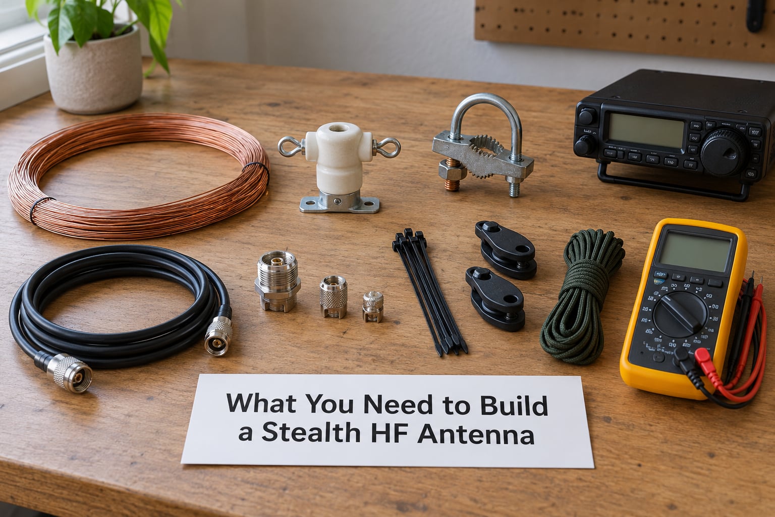
The list is short, and almost every choice depends on your available span, your soil, which bands you want, and whether the wire sits above ground or is buried. Nothing on it is exotic hardware.
- Wire: 20m to 100m of thin bare copper wire, 0.5mm to 1.5mm diameter. The thin, nearly invisible polystealth type is what most operators reach for when the wire will sit in view.
- Feedpoint insulator: one ceramic or acrylic standoff for a wire dipole, or a small waterproof box containing a 49:1 unun transformer for an end-fed wire.
- Supports: two or more short nonconductive posts, fence-post insulators, or screw eyes with plastic bushings. Fiberglass is a good choice; galvanized steel is not.
- Counterpoise wire: the same wire type, for a counterpoise and radials. Budget the same 20m to 100m again.
- Coax: enough to reach from the feedpoint to your radio, plus a few meters more than the direct route so the slack can be dressed neatly.
- Common-mode choke: a ferrite core or a stack of ferrite beads sized for the coax diameter, to sit at the radio end of the feedline.
- Ground hardware: a ground clamp, copper strap, and anti-corrosion compound. A proper earth connection also needs a rod or plate and a heavy gauge bonding conductor.
- Connectors: SO-239 or equivalent fittings, weatherproof cable glands, and self-amalgamating tape.
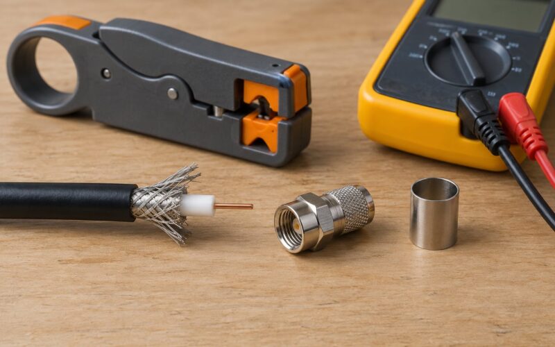
You also need a digital multimeter with an SWR or impedance function, an SWR bridge or a transceiver with a built-in SWR meter, a tape measure, a compass or phone app, and a pair of gloves. If any part of the job means digging, add a spade, an irrigation-line locator, and the phone number of your local utility-locating service before you touch the ground.
How to Build a Stealth HF Antenna for a Small Yard, Step by Step
1. Choose a safe, legal location
Walk the yard before you measure anything. Look for buried utility runs, irrigation lines, septic fields and drainage, and note any overhead power or telephone cables, metal fences, aluminum gutters, reinforced concrete and metal garden furniture. A wire running parallel to a fence or a power line for 20 meters will detune and partly waste the antenna.
Never guess where services run. Call the utility-locating service, and mark every line with paint or flags on the surface so you can see where the safe digging zone actually is. How you verify this step is simple: your marked route is clear, you know the required clearance from overhead conductors, and no part of the antenna touches anything a licensed electrician would warn you about.
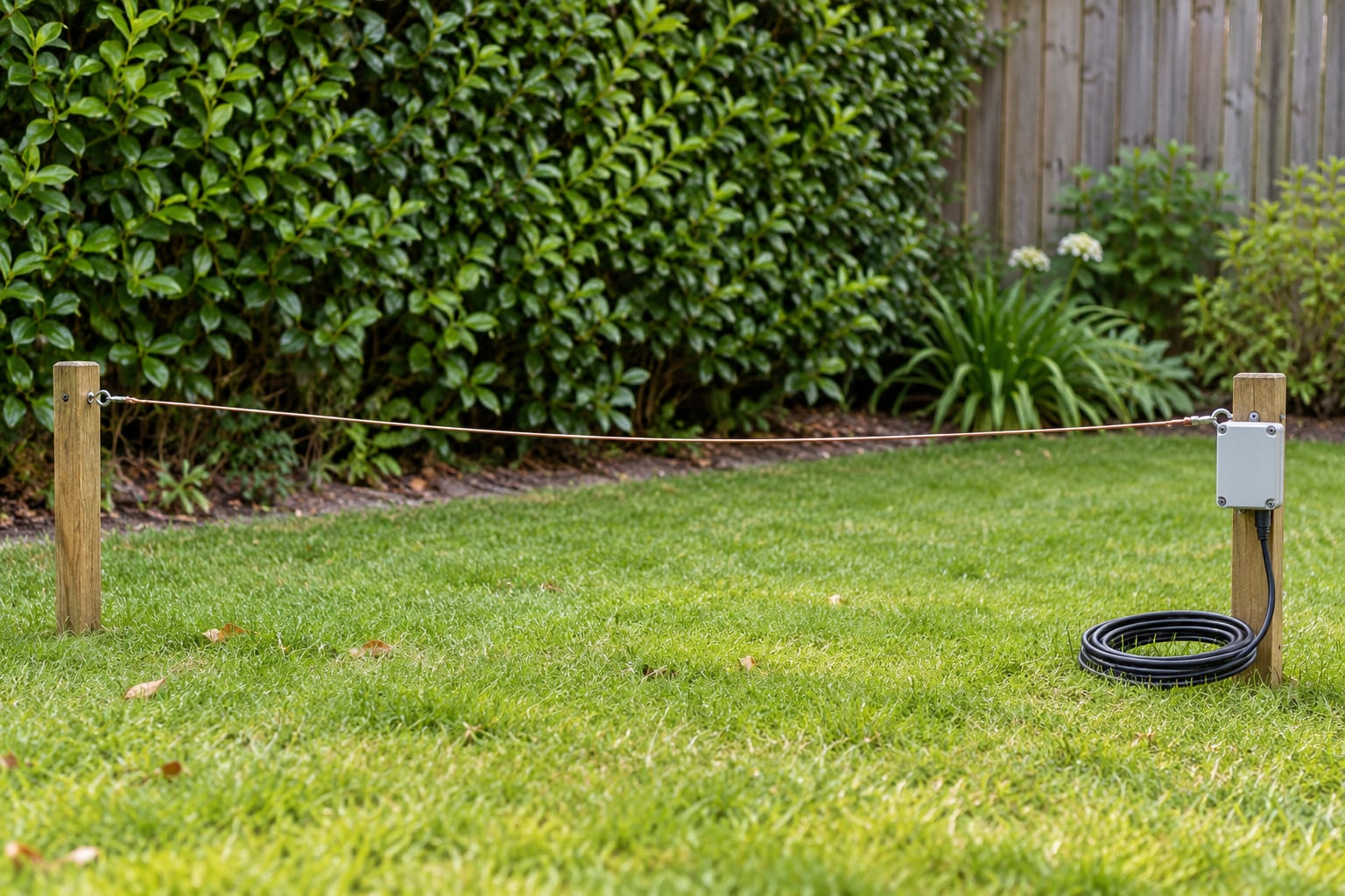
Check the rules before you build, not after. In the US, an amateur station is self-certifying, but local zoning, building permits for structures, and homeowners association covenants are separate matters that many associations do address explicitly. What makes an installation genuinely invisible, in practice, is a wire below hedge height that nobody can see from a neighbor’s window. What makes it visibly an antenna, almost always, is a mast, a dipole hung from a chimney, or a fence modification at eye level.
2. Select the antenna design and dimensions
There are three practical low-profile shapes, and the right one follows from your space. A horizontal wire above ground at hedge height is a dipole, and it is the best performer when you have the width. A sloped wire between two existing supports, such as a fence line and a tree, is the same dipole with more height and no mast. A vertical, often partly buried with a ground stake, needs a good counterpoise and radiates in all directions but concentrates its energy into a steep take-off angle.
For the horizontal and sloped options, size the wire with the standard half-wave calculation: 468 divided by the frequency in MHz gives the total length in feet, and 142.25 divided by the frequency in MHz gives meters. Halve that for each side.
- 80m (3.5 to 4.0 MHz): about 128 to 132 feet total, roughly 64 to 66 feet per side. Expect a small yard to be tight here.
- 40m (7.0 to 7.3 MHz): about 64 to 67 feet total, roughly 32 to 33 feet per side. This is the practical lower limit for most small yards.
- 20m (14.0 to 14.35 MHz): about 33 feet total, roughly 16 to 17 feet per side. This is the length that fits a compact yard without crowding it.
- 15m (21.0 to 21.45 MHz): about 22 feet total, roughly 11 feet per side.
- 10m (28.0 to 29.7 MHz): about 16 to 17 feet total, roughly 8 feet per side.
Cut to the low end of the band you intend to use, then trim. If your longest clear run is shorter than the number you calculated, an antenna modeling tool such as NEC or 4nec will let you try shortened and loaded versions before you commit to cutting anything. A loaded dipole trades some efficiency for a much shorter length; in a very tight yard that is usually a good trade.
3. Install the support and feedpoint
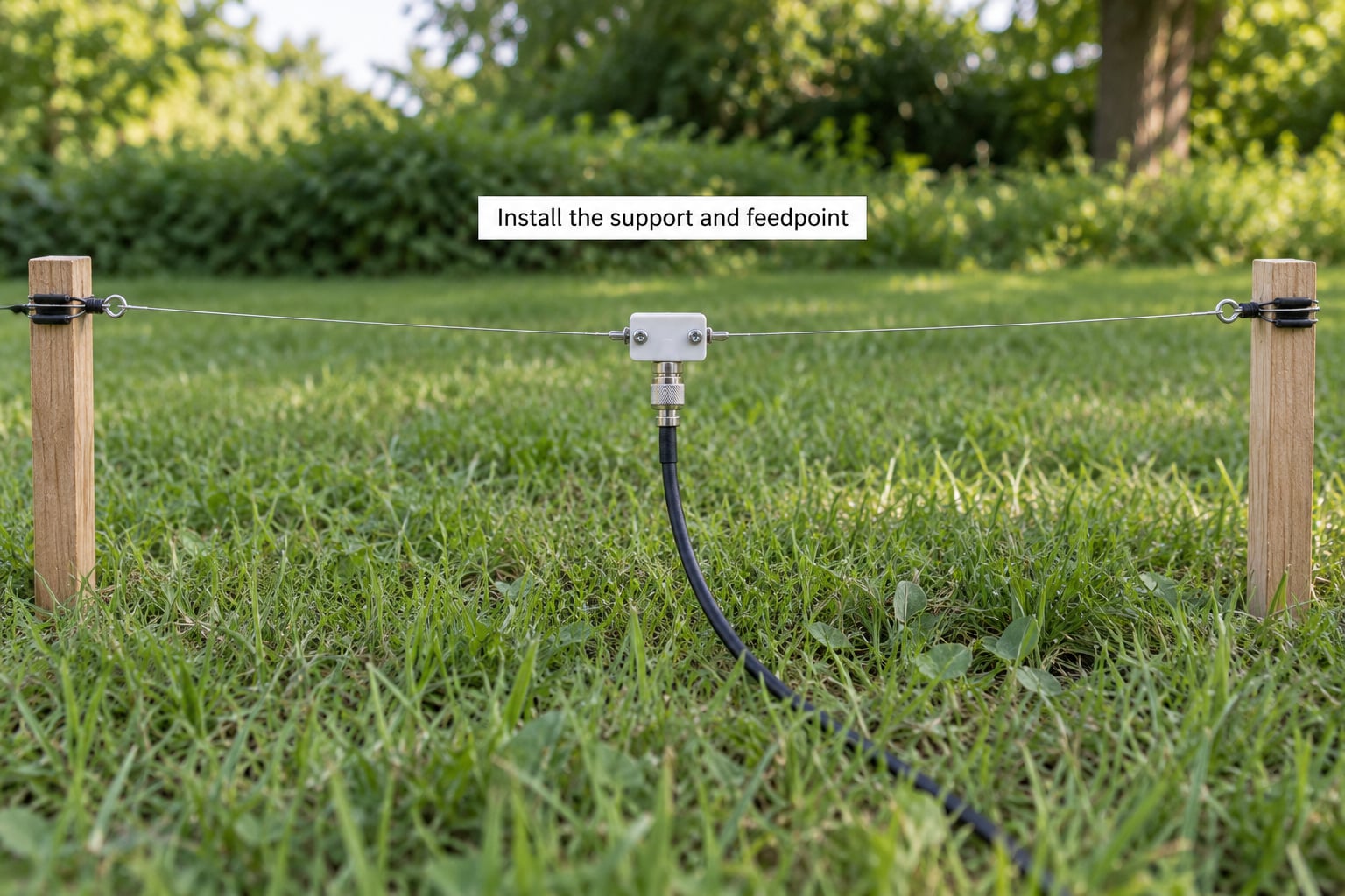
Mount each wire end on an insulator so the conductor never touches metal. Screw eyes with plastic bushings, or purpose-made fence-post insulators, are enough for a wire at hedge height. How you verify the mount is right: the wire sags slightly with no sideways tension, and the insulator is doing the electrical work rather than the post.
Keep real distance from metal gutters, downpipes, chain-link fencing, metal sheds and vehicle bodies. A fence can be used as a hint of a directional wire, but do not attach to it, and never solder or clamp a feedpoint to it.
For a center-fed dipole, bring the two wire ends to a single ceramic standoff and run the coax down and away. For an end-fed wire, put the 49:1 unun inside a small waterproof box, feed it with coax at one end and the single wire at the other, and mount the box where rain cannot reach the terminal posts. Seal it, then add strain relief so the coax cannot pull on the joint.
Some hard rules: do not connect an antenna to metal plumbing, to a drain pipe, to a mast you have not properly bonded, or to any part of the electrical wiring or an outlet. A window screen or a railing is not a ground. If a bonded structure seems like it would work, that is a job for a licensed electrician to assess first.
4. Install a safe ground or counterpoise system
This is the step most small-yard antennas skip, and it is the one that decides whether an end-fed works at all. An end-fed half-wave has a high feedpoint impedance that swings wildly across the harmonic, which is exactly what a 49:1 unun transforms down to something a transceiver can drive.
A counterpoise is not an earth. It is a system of wires laid out against or under the ground, and it becomes one half of the antenna. For a ground-mounted vertical, a single buried copper wire running outward at low depth, or a fan of 0.5 to 1 wave of wire, gives the radiating element something to work against. A portable setup can use a counterpoise laid on the surface, weighted with stones or pegged under turf.
A true earth connection means a conductor, sized for the installation, bonded to a ground rod or plate driven to the depth your local code specifies. It matters for lightning protection and for keeping the shack stable during transmit, and it is the reason your radio’s chassis ground and the antenna ground should be bonded together at a single point. Any connection to a building’s grounding system, a mast, or a metal structure should be reviewed by a qualified electrician before you make it.
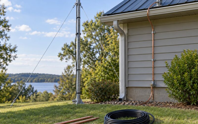
Protect the metal. Use stainless or tinned hardware, wrap bare connections with self-amalgamating tape, and leave nothing buried in a soil that will rot a copper clamp in a year. Route the feedline along the same path as the antenna or use a ferrite common-mode choke at the radio end, so the outside of the coax does not become a second antenna and carry RF into your house.
5. Connect the radio and tune the stealth HF antenna
Run the coax from the feedpoint to the radio, keeping it as short as the yard allows and away from the antenna wire for as much of its length as you can manage. Put the common-mode choke at the shack end, with two or three turns of coax through the ferrite, and bond the radio chassis to the ground system at that same end.
Match the antenna to the transceiver. Use a 49:1 unun when you are feeding an end-fed wire, an antenna tuner when the length cannot be trimmed accurately or you want several bands from one wire, and neither when the dipole is at a half-wave length in the middle of the band you care about. Tuning an antenna through a tuner hides a badly matched length rather than fixing it, so trim first and use the tuner for the rest.
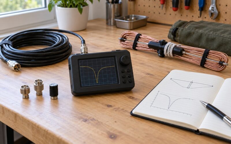
Then measure. Set the radio to low power, check SWR at the low end of the band, move up the band in small steps, and record where the minimum sits. If the SWR dip sits below your target band, the wire is too long; shorten it by small increments, coil the excess rather than cutting on the first attempt, and repeat. Ten minutes of this loop saves replacing a length that was never right.
No particular SWR figure is guaranteed before you build. The same wire in a different yard, next to a different fence, will give a different reading, and neighboring buildings can shift it. Tune what you actually have.
6. Test the installation under real operating conditions
Start with a few watts and a short transmission, with the radio at the same operating position you will use normally. Watch the SWR reading while you transmit, and check a nearby receiver, television or audio device for any sign of interference. If the transmitter protects itself, drops output, or the SWR jumps when you speak, stop and find the fault before you increase power.
Compare reception against a reference. Tune a shortwave station or an AM broadcast on the wire antenna and then on a reference receiver, and note the noise floor difference. A low wire in a suburban yard will usually hear more local electrical noise than a small magnetic loop, because the loop is more selective against that noise; the wire wins back the advantage on transmit, where the loop loses efficiency quickly, especially toward 40m.
Then listen for RF feedback. If the S-meter jumps when you transmit, the audio warbles, or your transceiver’s supply voltage dips, suspect common-mode current on the feedline and fix the choke and grounding before anything else. Reduce power or stop until it clears. This is a solvable problem, but not one to experiment with at full output.
Common Mistakes That Break a Stealth HF Antenna
Attaching to a metal fence or gutter and calling it done. Metal is a conductor. Whether the joint works depends on the fence’s length, height, grounding and the soil around it, none of which you can predict. Use the structure as a landmark for where your wire runs, not as the antenna itself.
Skipping the counterpoise on an end-fed wire. This is the most common reason a compact vertical or an end-fed is disappointing. Give it 0.5 to 1 wavelength of counterpoise wire, and check the system with a tuner as you vary its length.
Cutting the wire to a published number and stopping there. Published lengths assume free space. Your roof, fence and neighbors change the result. Cut long, measure, trim in small increments.
Leaving the coax unchoked. The outer shield of an unbalanced feedline becomes a radiating surface. Two or three turns through a ferrite at the radio end often remove most of the RF in the shack problems people blame on the antenna.
Running the wire too close to metal. Detuning is quiet and confusing. Keep clear of gutters, fences and roofs where you can, and re-measure SWR if you move the wire even a foot.
Ignoring the neighbor problem. Most objections come from a visible structure, not from interference. Wire at hedge height, painted supports in a color that blends, and modest power remove nearly all of it. Low power, from QRP up to around 70 watts, is a deliberate choice here rather than a compromise, and it is the level at which a hidden wire still lets you work a pile-up.
Building permanent on the first attempt. Run a temporary low-power version first, a wire draped between two chairs or over a fence, and learn what your site does before you mount anything. Moving a temporary antenna is fast; moving a permanent one is not.
Frequently Asked Questions
Can a small yard really work for HF and DX?
Yes, with honest expectations. A low wire radiates a steeper take-off angle, which favors long and medium paths rather than knife-edge grazing contacts, but plenty of operators run hidden wire from attics, eaves and fences and work real DX. The antenna does not need to be high to be useful; it needs to be correctly resonant, properly fed, and free from nearby metal.
Is a buried wire antenna legal and practical?
Buried wire is usually fine, but call your utility-locating service before you dig and check whether a local permit applies to any part of the route. It is very well suited to end-fed and vertical systems, where a buried radial or counterpoise replaces an above-ground wire. Plan for access with an auger, and use direct-burial rated wire and tape at any joint.
Should I use a wire dipole or a magnetic loop?
A wire dipole is simpler, cheaper, handles transmit power easily and works best on the bands you can actually cut to length. A magnetic loop tolerates very restricted space and has much better noise rejection on receive, but it is narrow-band, loses efficiency toward 40m and needs careful tuning. For a small yard you can span, start with wire. For a patio or balcony, a loop.
What tuner or matching network do I need?
Use a 49:1 unun if you are feeding a half-wave end-fed wire, since its feed impedance is high and varies sharply across the harmonic. Use an antenna tuner when the wire length cannot be trimmed accurately, when you want several bands from one wire, or when a tuner lets you trim rather than cut. A properly sized dipole in open space needs neither.
How do I feed the antenna without running a visible coax across the yard?
Run the coax along a fence line, behind a hedge, or underground in a shallow trench with direct-burial rated cable. Feedline dressed along the same path as the antenna wire is much harder to spot than a line cut across open grass. Add a ferrite common-mode choke at the radio end so the coax shield does not pick up RF and put it into your house.
Can the same wire serve an attic or eaves installation?
Yes, and it is one of the most reliable low-conflict options. Run a loop under the eaves on nonconductive standoffs all the way around the house, or use attic rafters, and bring the feedline in through a soffit vent. Watch the roof covering and use screw eyes rather than drilling into shingles, and re-check SWR once the roof is wet.
Conclusion
Start by surveying the yard, marking every buried and overhead service, and picking the one band you most want to work. Cut that wire long, run it temporarily at low power, and let the meter tell you how much to trim. Once it is resonant, add the counterpoise, choke the feedline, and only then make it permanent and invisible.
Keep the installation inside the rules that cover your property, keep the power modest, and trust the measurements over any number printed in a guide. That loop, repeated a few times, is the whole craft.