To make a 1:1 choke balun with coax, run a measured length of 50-ohm cable through a ferrite core or form a coil with it so the cable makes several passes through the core, then terminate both ends so the outer shield current is blocked while the inner signal passes untouched. It takes about an hour and needs only cable, a core or a plastic form, connectors and cable ties.
The whole trick is that a coil of coax looks like a transformer to RF current on the outside of the braid. That current goes through the core aperture in one direction, so the ferrite presents a high impedance to it and pushes it back. The signal current you actually want runs down the centre conductor and back along the inner braid, equal and opposite, and cancels itself in the aperture.
You need one if a dipole, inverted-V or end-fed wire on coax keeps putting RF into your shack, into neighbouring electronics, or into your own receive audio. If your antenna is symmetric and your coax runs cleanly away from metal, you probably do not need one at all.
Table of Contents
- 1What You Need
- 2Step-by-Step: How to Make a 1:1 Choke Balun with Coax
- 3Step 1: Choose the Coax and Choke Core
- 4Step 2: Determine the Coax Length and Turn Count
- 5Step 3: Wind the Choke Evenly
- 6Step 4: Terminate and Mount the Balun
- 7Step 5: Test the Balun and Check the Feed Point
- 8Common Mistakes
- 9Frequently Asked Questions
- 10How many turns of coax do I need for a 1:1 choke balun?
- 11Which coax is best for a homemade coax choke balun?
- 12How many feet of coax do I need for the choke?
- 13Does a 1:1 choke balun reduce RFI?
- 14Where should the choke go on a dipole?
- 15Should I buy a commercial 1:1 choke instead of building one?
- 16Conclusion
What You Need
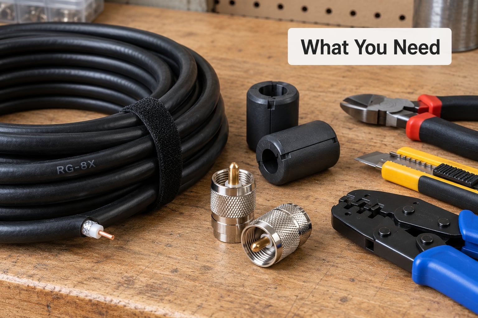
Four things decide whether a homemade choke works: the coax, the core, the number of turns and the coax length. Everything else is cable ties and patience.
Coax. Any real 50-ohm cable will build a choke, but the diameter decides how gently you can wind it. RG-213 and RG-400 are the easiest on a small toroid because they bend easily. RG-8X is the common choice for broadband HF chokes. RG-58 works, but its tight bend radius is the single most common reason a small choke gets built badly. Avoid foam-insulated cable for anything you plan to leave up; the failure is slow and invisible.
Core. For 10 to 30 MHz, two FT240-31 or FT240-43 toroids are a solid starting point, and mix 31 is also fine below 10 MHz where mix 43 loses permeability fast. Below about 3.5 MHz the wire-wound or PVC-form choke beats a small toroid, because the toroid simply cannot hold enough inductance. Use solid PE coax rather than foam for the same reason the geometry stays stable.
Connectors and hardware. PL-259 plugs or SO-239 sockets to match your radio, heat-shrink tubing, cable ties or small hose clamps, a length of self-amalgamating tape or self-adhesive vinyl for weatherproofing, and a permanent marker for labelling.
Tools. A coax stripper or a sharp knife and soldering iron for PL-259, a multimeter, a tape measure, and an SWR meter or antenna analyser if you have one.
Cable length is not an afterthought. One experienced builder on the antenna boards winds his HF chokes from roughly 23 to 25 feet of coax on a one-gallon container, and commenters regularly point out that people run out of cable before they reach the turn count they need. Buy more than your first calculation suggests.
Step-by-Step: How to Make a 1:1 Choke Balun with Coax
Step 1: Choose the Coax and Choke Core
Start with 50-ohm coax matched to your power. Under 100 watts, RG-58 or RG-8X is fine. At 500 watts and up, move to RG-213 or RG-400, which also handle heat better. Then pick the core for your band: FT240-31 for 3.5 to 30 MHz, mix 43 if you want a bit more loss in a coil used at low power, and a larger ferrite such as an FT240 or a stack of 43 beads if you need more choking impedance on 160 metres.
Step 2: Determine the Coax Length and Turn Count
You need enough cable for the choke plus whatever length reaches from the choke to your radio, so measure the run first and subtract. For the choke itself, the common rule of thumb is that choking impedance should be around ten times the feed point impedance, so a 50-ohm feed wants something in the hundreds of ohms. Treat the numbers below as starting points, not answers.
| Band | Coax | Starting turns | Coil diameter | Core |
|---|---|---|---|---|
| 80 and 160 m | RG-213 or RG-8X | 15 to 20 | 8 to 10 inch | None, or large ferrite |
| 40 and 80 m | RG-213 or RG-8X | 8 to 10 | 6 to 8 inch | 2 x FT240-31 |
| 20 and 40 m | RG-8X | 6 to 8 | 5 to 6 inch | 2 x FT240-31 or FT240-43 |
| 10, 15 and 20 m | RG-8X | 4 to 6 | 3 to 4 inch | 1 to 2 x FT240-43 |
| 6 m and VHF | RG-58 or RG-8X | 3 to 5 | 3 to 4 inch | 3 type-43 beads or 1 small toroid |
Notice the coil diameter grows as the frequency drops. Inductance scales with the square of the turn count and with the area enclosed by the turns, so ten tight turns on a two-inch toroid do not behave like ten loose turns on a six-inch coil.
Step 3: Wind the Choke Evenly
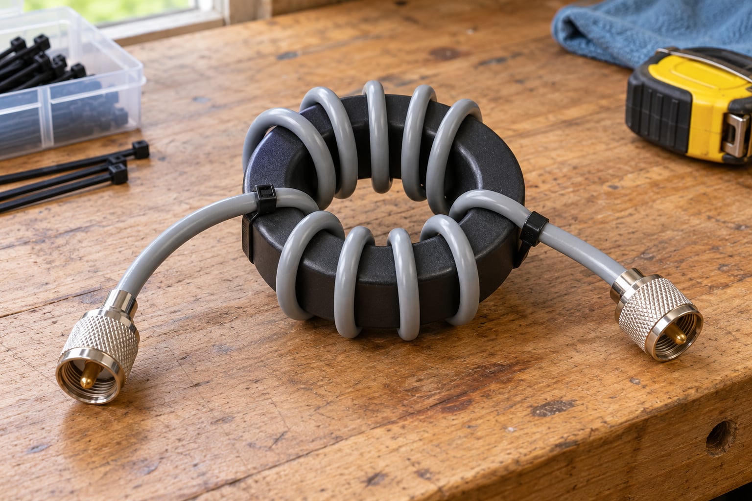
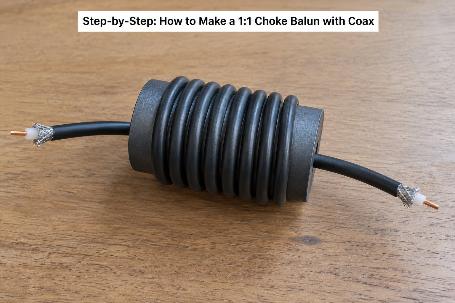
For a toroid build, count each pass through the hole as one turn and keep going in the same direction around the core. Space the passes evenly and leave the cable lying flat against the ferrite rather than pinched between turns. Stop short of the datasheet minimum bend radius for your cable; a wide diameter helps more than extra turns.
There is a persistent argument online about tight windings. A commenter on the build threads makes the standard correction: choke inductance barely changes whether the turns are snug or loose, because the same net current passes through the core either way. Keep the windings loose enough to survive weather and handling.
For a PVC or tub build, wind a single layer with a small gap between turns and secure each pass with a cable tie. Do not pile turns on top of each other; adjacent turns act as a capacitor and the choke can self-resonate below your operating band.
Step 4: Terminate and Mount the Balun
Fit connectors before the choke goes outdoors. With PL-259 plugs, slide the barrel and the spacer or split washer onto the coax first, then solder the braid to the barrel, slide the plug body over it, and solder the centre conductor to the pin. Solder the barrel last and solder it to the braid at two or three points so it cannot rotate or pull out.
Strain-relieve both ends with heat-shrink and a tie to the coax jacket, never to the coax itself. Leave a drip loop below each connector. Mount the choke where it cannot touch metal, and keep it at least an inch or two clear of a mast, a roof edge or a metal fence, because a choke that touches a conductor is a different circuit.
Make sure nothing bridges the choke. The point of the device is that the shield current stops there; if the coax continues past the choke and touches the antenna or the mount, current simply flows around your work.
Step 5: Test the Balun and Check the Feed Point
Before it goes up, put the multimeter on continuity and confirm a solid DC path along the shield from end to end. A 1:1 choke does not break that path; a DC-continuity failure means a connector or a joint is wrong.
Then check SWR into a known-good dummy load or with the antenna disconnected, and confirm the choke does not add measurable loss. The honest test of a choke is an RF current probe clamped around the coax on each side of it: you should see the current drop sharply on the antenna side. SWR alone proves nothing about common-mode suppression, since a well-matched antenna can still be radiating from its feed line. Write the band and the turn count on the choke body with the marker before it goes outside.
Common Mistakes
Too few turns, or turns bunched in one place. Add passes through the core rather than tightening what you have. Uneven spacing concentrates the inductance in one spot and can self-resonate below your band.
Winding tight until you violate the bend radius. This is the most-upvoted question on the antenna forums. Look up the minimum bend radius in the cable datasheet and widen the coil instead of squeezing it. Repeated sharp bends are what push the centre conductor through the insulation.
Using foam-insulated coax. Cheap, and a bad idea here. Foam lets the centre conductor migrate under repeated bending, and the impedance drifts slowly before anything visibly fails.
Wrong core for the frequency. A type-43 bead choke that works on 20 m does very little at 80 m. Below about 3.5 MHz, use a large coil or a big ferrite, not a snap-on bead.
Letting the shield contact the antenna or the mounting hardware. That shorts out the very path the choke is meant to block. Use standoff hardware and keep the coax clear of metal.
Poor grounding at the shack. If the noise is arriving through your house wiring, a feed point choke will not fix it. Bond the station and check the coax entry point before blaming the antenna.
Wiring the connectors backwards. Centre conductor to pin, braid to body. A dry joint inside a PL-259 shows up later as an intermittent SWR jump that looks like a bad feed point.
Judging the result by SWR alone. A choke that does nothing to SWR may be doing its job well. Measure common-mode current, or at minimum compare receive noise and RFI behaviour with and without it.
Frequently Asked Questions
How many turns of coax do I need for a 1:1 choke balun?
For 20 metres, six to eight turns of RG-8X on a two-toroid choke is a common starting point. On 40 metres go to eight to ten turns, and on 80 metres use fifteen to twenty turns on a six to ten inch coil diameter. Choking impedance rises with the square of the turn count, so diameter matters as much as turns. Treat these as starting values and confirm with a current probe.
Which coax is best for a homemade coax choke balun?
RG-213 or RG-400 is easiest to wind because both bend readily on a small toroid. RG-8X is the usual broadband HF choice and handles more power than RG-58. Use solid PE insulation rather than foam, since repeated bending can push the centre conductor through foam insulation and change the impedance. Match the cable to your power level and to the minimum bend radius in its datasheet.
How many feet of coax do I need for the choke?
For an HF broadband choke, builders commonly use twenty-three to twenty-five feet of cable wound on a one-gallon container, which gives room for fifteen or more turns plus mounting slack. Subtract your feed line length from your total roll first, then buy more than the calculation leaves you with. Running short is the reason many first chokes come out with too few turns.
Does a 1:1 choke balun reduce RFI?
It does when the RFI is caused by current on the outside of your coax shield. That current radiates and couples into audio gear, computers and neighbouring electronics. A choke at the feed point removes it there, and a second choke at the radio end or the building entry cleans up whatever is left. If the interference originates in your own wiring, a choke will not help.
Where should the choke go on a dipole?
Put it right at the antenna feed point, as close to the terminals as you can manage, so the shield current has nowhere to go before it reaches the coax. A second choke at the radio end or where the coax enters the building catches what gets past it. Keep the two chokes far enough apart that the coax between them cannot act as a separate radiator.
Should I buy a commercial 1:1 choke instead of building one?
Buy one if you need a guaranteed choking impedance figure across a wide band, if you run high power continuously, or if you want the device to be compact for a portable setup. A homemade coax choke is hard to beat for a fixed dipole on a modest budget, and the parts are the ferrite and cable you would buy anyway. The label matters less than the specified common-mode impedance.
Conclusion
Start by measuring your feed line and buying enough solid-PE coax for both the run and the turns. Wind evenly, keep the bend radius honest, terminate the connectors in the right order, then check the feed point with a current probe at your intended operating frequencies before the choke goes outside. If the shield current does not drop, no amount of extra turns will rescue it, and the problem is somewhere else in the antenna.