An end-fed wire presents a few thousand ohms at its feedpoint, and a 50-ohm transceiver will not feed it directly. To answer how to build an unun for an end fed antenna in one line: wind a two-winding transformer on a ferrite toroid, most often 2 turns on the antenna side and 14 on the coax side, box it, and terminate the coax. The transformer steps that high feedpoint impedance down so the radio sees roughly 50 ohms and little power is reflected back.
It is a bench project, not a major build. An hour of winding, an hour of boxing, and an afternoon of measuring will get you a unit that works for years, provided you check the ratio against your actual antenna rather than against a wire length from someone else’s website.
One distinction to settle before you buy a core. A 9:1 unun suits random-length wire that needs a tuner, while a 49:1 unun suits a resonant end-fed half-wave (EFHW) that works on its fundamental band and the harmonics. People mix those two up constantly, and the mix-up is the reason so many first builds come back with unusable SWR.
Table of Contents
- 1What You Need: How to Build an Unun for an End Fed Antenna
- 2Which ferrite core to buy
- 3Step-by-Step
- 41. Choose the Unun’s Intended Impedance Ratio
- 52. Measure the End Fed Antenna’s Impedance
- 63. Calculate the Primary and Secondary Turns
- 74. Wind the Transformer on a Suitable Core
- 85. Mount and Terminate the Unun Safely
- 96. Test the Unun Before Connecting a Transmitter
- 107. Tune the Antenna at Lower Power
- 118. Verify Performance and Document the Design
- 12Common Mistakes
- 13Frequently Asked Questions
- 14What turns ratio do I need for my end fed antenna?
- 15Is a 4:1 or 9:1 unun better for a half-wave end fed antenna?
- 16What ferrite core should I use to build an unun?
- 17Can I use a homemade unun for portable and QRP operation?
- 18How much power can an unun safely handle?
- 19Conclusion: Measure First, Then Wind
What You Need: How to Build an Unun for an End Fed Antenna
The transformer itself is cheap. What decides whether the project succeeds is the test gear, because an unun that is off by a few percent of ratio behaves like a random length of wire.
Ferrite toroid. One large core is enough for QRP and most 100-watt single-band work. Size follows the band and the power, not the ratio.
Enamelled copper wire. 20 AWG to 24 AWG works well. Thinner wire is fine at low power, heavier wire buys little once you are past about 100 watts.
Enclosure. A small ABS or plastic project box with a lid. Outdoor sites want a sealed box with a cable gland rather than a screw-together plastic case.
Feedline connector. An SO-239 chassis mount for permanent installations, a BNC socket if you want a small box for portable work, plus the matching plug or a panel-mount adapter.
Antenna and counterpoise terminals. A terminal post, binding post, or a pair of solder lugs on the box wall, so the wire and the return are mechanically secure rather than held by a solder joint alone.
100 pF 3 kV ceramic capacitor. Not used in every design. A differential or parallel-wire feed needs one, and a 9:1 design that relies on a matching coil needs it too. The voltage rating is not optional; RF voltage at the antenna end of a half-wave is far higher than your transmitter’s output power suggests.
Heat-shrink tubing, PTFE tape, cable gland, small hardware. Plus a strain-relief point for the antenna wire so a gust does not work the terminal loose.
An antenna analyzer and a 50-ohm load. This is the item people skip. An analyzer tells you the impedance the antenna system actually presents; a known 50-ohm dummy load tells you whether your transformer is doing its job. Guessing at either one is how projects end up on the shelf.
Choke material. A handful of ferrite beads on the coax, or a clamp-on ferrite core, for common mode control after the antenna is up.
Hand tools. Soldering iron, multimeter with continuity, side cutters, and a small square or ruler for counting turns.
Which ferrite core to buy
| Core | Typical use | Notes |
|---|---|---|
| FT140-43 | QRP, 5 to 15 watts, single band | Small and light. Advice on the groups.io QRP Tech list recommends exactly this core with a 3-turn primary, 21-turn secondary and 18 AWG wire for a 49:1 QRP build. |
| FT240-43 | 20 m and up, up to about 100 watts | The general-purpose choice for HF. Handles the higher bands without the losses a low-frequency mix brings. |
| FT240-52 | 80 m, 40 m, 30 m | Higher permeability material that works better on the low bands where mix 43 struggles. |
| FT240-61 | 40 m and 30 m, or a step up in power handling | A compromise between the low-band and high-band mixes, popular for 100-watt plus builds. |
One UK builder on the Charlie Tango DX forum runs a 49:1 on three FT240-52 cores cut for 80 m and works it horizontally, mostly on 40 and 80 m. That is the stacked-core route, and it is worth knowing about if you plan to run digital modes at full power on a single core.
Step-by-Step
1. Choose the Unun’s Intended Impedance Ratio
Start by deciding what the transformer is for, because the ratio follows from the antenna rather than from the box you want to fill.
A half-wave end-fed wire has a high-impedance feedpoint, commonly in the range of 2,500 to 5,000 ohms depending on height and surroundings. Stepping that down toward 50 ohms is the whole job, and the arithmetic gives the popular ratios: 2,500 to 5,000 ohms is roughly a 49:1 to 100:1 step, which is why 49:1 is the default for an EFHW.
A random-length wire has no predictable feedpoint impedance at all, which is the point of a random wire. A 9:1 unun there simply gives the tuner a sane starting point, and the tuner does the rest.
Two things this is not. It is not impedance matching in the LC sense; there are no capacitors doing the conjugating work unless you add one for a specific design. And it is not a guarantee that any end-fed wire will work. Measure first, then choose the ratio.
2. Measure the End Fed Antenna’s Impedance
Install the antenna the way it will actually run: intended wire, intended supports, intended counterpoise, and the same neighbours it will live beside. An impedance measured flat on a workbench with the wire coiled up tells you nothing useful.
Nearby metal, a roof, a fence, and the ground conductivity under the wire all move the feedpoint impedance. So does the height. This is why an EFHW cut for 40 m on a hillside can behave differently at home.
Then look at the harmonic bands. An EFHW resonated on 40 m will usually be close to usable on 20, 15 and 10, but the impedance at each harmonic is not identical, and the same ratio will not transform every one of them equally well.
Note the impedance at the planned feed point with the analyzer, on every band you intend to use, before the transformer exists. That number is what the turns count in step 3 is calculated from.
3. Calculate the Primary and Secondary Turns
The rule is short enough to memorise. Divide the antenna-side impedance by 50 ohms, then take the square root, and that gives you the turns ratio between the two windings.
Ns / Np = square root (Zantenna / 50)
Worked example for an EFHW. With a 2,450-ohm feedpoint, 2,450 divided by 50 is 49, and the square root of 49 is 7. A 7:1 turns ratio is what you wind, so the common forms are 2 turns on the primary and 14 on the secondary, or 3 and 21.
A 9:1 impedance step gives a turns ratio of 3, so 3 turns and 9 turns. A 64:1 step gives 8:1, which is 2 and 16.
| Impedance ratio | Turns ratio | Primary turns | Secondary turns | Notes |
|---|---|---|---|---|
| 9:1 | 3:1 | 3 | 9 | Random-length wire with a tuner |
| 16:1 | 4:1 | 2 | 8 | Short feed with added matching |
| 25:1 | 5:1 | 2 | 10 | Occasionally used for lower bands |
| 49:1 | 7:1 | 2 | 14 | Standard EFHW build |
| 64:1 | 8:1 | 2 | 16 | Not the same as 49:1, see common mistakes |
Small integer ratios are convenient, not exact. Two and fourteen gives exactly 49 in theory; a real toroid with uneven winding, lead length, and the loading the wire adds will not sit precisely on that number. This is why step 6 exists.
Round to whole turns, and round down rather than up when you are between two options. A transformer with slightly too little ratio on a high-impedance feed leaves more of a mismatch on the antenna side, which the tuner can often trim away, whereas too much ratio pushes the presented impedance past what the wire can support. Where the arithmetic lands on a fraction, 3 and 21 is usually a friendlier starting point than 2 and 14 for the same 7:1, because more turns means finer adjustment when you change the wire length later.
Wire length is not the input to this calculation. A common wire length with the wrong ratio is still the wrong ratio, and no amount of adjusting the counterpoise will fix it.
A note on topology, because the terminals are wired differently depending on which you build. The straightforward EFHW uses a single-wire radiating section with the unun stepping that wire’s impedance down to the coax, and the coax braid bonds to the antenna-side terminal. A differential or parallel-wire feed runs the two halves of the antenna to the two antenna-side terminals instead, which is why those designs need the series 100 pF to 470 pF capacitor to set the impedance rather than the winding alone. If your box has two antenna terminals, that is the second kind.
4. Wind the Transformer on a Suitable Core
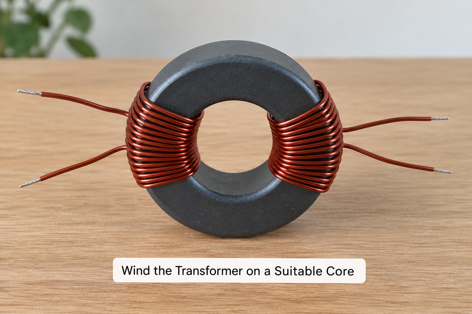
Cut roughly a third more wire than the total turn count needs, then strip and tin about 15 mm at each end. Tinning first means you are not trying to solder a slippery enamel edge while the core is already threaded.
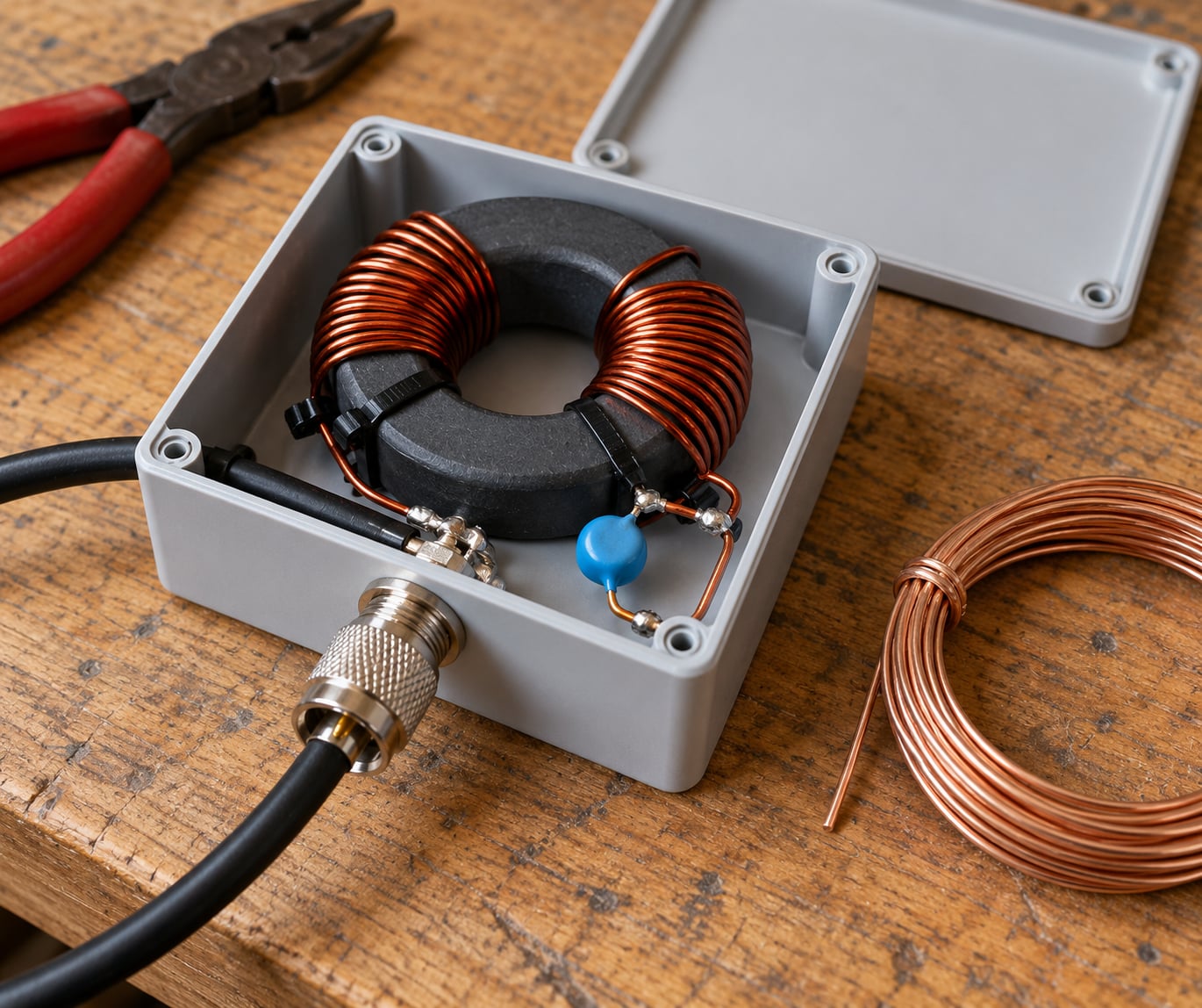
Start the secondary first, passing it through the core the full number of times. Then wind the primary in the same direction, keeping both wires as close together as the core window allows. A bifilar primary, where two legs run side by side through the hole, reduces capacitance between the windings and behaves better at the top of the band.
Keep the winding even. Space the passes evenly around the torus, keep the tension the same on every pass, and avoid a sharp bend where the wire leaves the core. A lumpy winding is not only ugly; uneven turns mean uneven leakage inductance.
Count passes, not holes. Threading the wire through the hole ten times makes ten turns, and the widely-shared build that claims 2 primary and 16 secondary for a 49:1 is a 64:1 transformer. Write the count on the core with a marker before anything gets soldered.
So the three builds most people want: an FT140-43 at 5 to 15 watts for portable and QRP work, a single FT240-43 or FT240-61 at up to about 100 watts SSB for a fixed single-band installation, and stacked or larger cores for sustained CW and digital modes at full power. Charlie Tango forum members make the same split when they describe a 140-size core handling 100 watts SSB at normal duty cycles, while digital modes and CW at that power want a bigger or stacked core. One builder there runs a 49:1 on three FT240-52 cores cut for 80 m, which is the shape of the fix when the duty cycle is heavy.
Against a commercial unit, the honest answer is that a homebrew unun is not automatically worse. A well-wound 49:1 on a good core performs comparably to a bought one, and you get the turns count you actually wanted. Where the money is worth spending is convenience and a known ratio, particularly on a 9:1 for random wire, where one forum user bought a commercial 9:1 with 20 m of wire rather than build one and made no apology for the choice. Build it if you want to, or buy it if the time is the constraint.
Core size, material, band and power all matter here. A core that is too small for the power saturates, and a saturated core loses its transformation ratio, which shows up as a hot toroid and an SWR that will not come down no matter what you change outside.
5. Mount and Terminate the Unun Safely
Fix the core inside the box so it cannot shift, then mount the connector and terminals. Keep the antenna-side winding and its terminal away from the coax connector by as much as the box allows, because that separation is what keeps common mode current off the feedline.
Bring the antenna wire in through a strain-relief point, not through a sharp hole in the box wall. Dress the leads so nothing pulls on a solder joint, and cover the exposed antenna-side conductor with heat-shrink before it goes near anything metal.
Where the transformer sits outdoors, run the coax through a common mode choke. Operators on the Charlie Tango forum place it roughly 1 to 2 metres back from the transformer at mast height, alongside a lightning arrestor, and run LDF450 coax back to the shack. A 49:1 unun does nothing for common mode current, so this is a separate part of the job.
Run the antenna and counterpoise before the transformer goes in. A half-wave end-fed antenna has no ground connection in the conventional sense: what it needs is a return, and that is the counterpoise. Without one, the antenna looks for a return path through the coax shield and the building, which is where high SWR, unstable readings and interference come from.
For a single-band end-fed half-wave, a counterpoise of roughly a tenth to a twentieth of a wavelength is the usual starting point, so 2 to 4 metres on 40 m. It is not a critical length in the way the radiating section is. Trim it the way you trim the wire: move it, measure, and watch where the SWR minimum and the receive noise settle.
Where the return goes matters as much as its length. A counterpoise running low over good soil behaves differently from one strung out horizontally, and a rooftop install tells a completely different story from a tree. Confirm the site will support a return at all before you cut wire for anything else.
Keep the box away from sensitive receive equipment, and do not route the antenna wire parallel to the coax for long distances. Now the safety point that gets missed most often: a low-voltage build still produces lethal RF voltage at the antenna end during transmit. Do not touch the wire or the terminal while transmitting, and do not assume a watertight box is also an insulated one.
6. Test the Unun Before Connecting a Transmitter
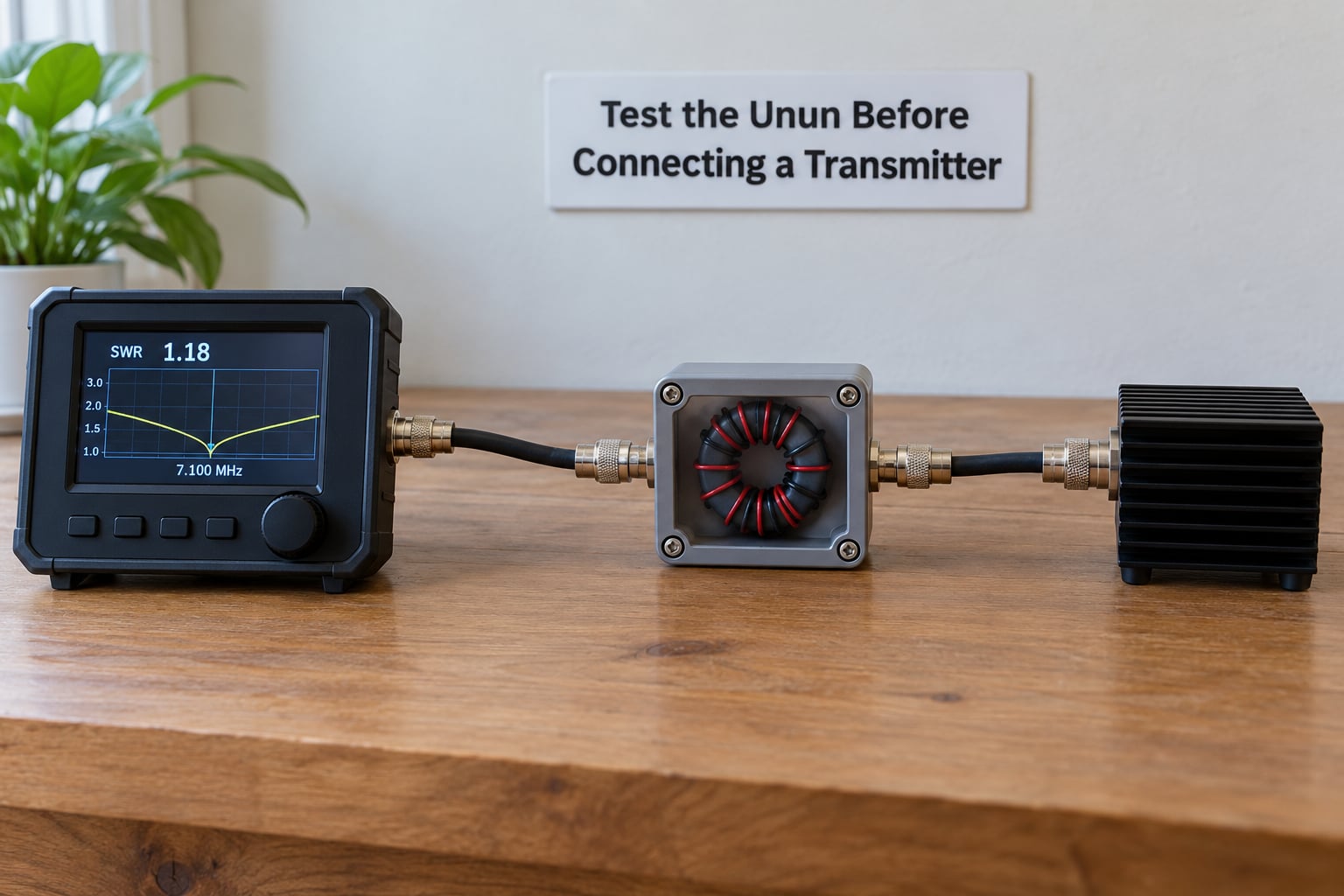
Check continuity through each winding with the multimeter before anything else. A short between windings means the insulation gave out somewhere, and a reading near zero ohms across a winding that should be a few ohms means the wire is damaged.
Then run the whole assembly into a 50-ohm dummy load and watch what the analyzer says on the target band. A correct transformer presents close to 50 ohms to the load side. If the analyzer is set to the wrong range for the impedance you are trying to measure, the reading is meaningless, so confirm the range before you trust the number.
Establish a repeatable baseline and write it down: the impedance, the SWR, the frequency, and the analyzer range. That single recorded measurement is what you compare against after every change you make in steps 7 and 8.
Define the pass condition before you go further. A reading within a few percent of 50 ohms on the low side means the ratio is close; a reading far from 50 tells you to go back to the winding and the count, not to start adjusting the antenna.
Do not tune or transmit into an unverified transformer, and use a properly rated dummy load rather than a piece of coax or an antenna you have not checked. If your setup involves anything mains-powered, get a qualified person to look at it.
Before the transformer goes near the antenna, run this list: turns counted twice and the ratio arithmetic checked, windings tested for continuity and for a short between them, antenna and counterpoise terminals secure and strain-relieved, coax choke fitted if the box is outdoors, and a written baseline reading in hand. Every item on that list costs a minute at the bench and saves an afternoon up a ladder.
7. Tune the Antenna at Lower Power
Move from the dummy load to the installed antenna and measure each band you care about, starting with low power. The fundamental band comes first; the harmonics come after that one is right.
To trim wire on an EFHW, move the junction between the radiating section and the matching section, not the end of the wire. Each step moves resonance, and the SWR minimum tells you which direction. Take small moves, and re-measure after each one.
Record what you change. The counters and lengths in the notes are the difference between a design you can rebuild next year and a mystery box that worked once.
Harmonic bands transform differently through the same ratio, and a ratio that is correct on 40 m will not produce a perfect match on 15 m. When the harmonic bands look poor, a small series capacitor of 100 to 470 pF in the matching section is the usual adjustment. A bigger unun ratio is not a substitute for an antenna that is not resonant where you think it is.
8. Verify Performance and Document the Design
Run the intended bands and check four things: SWR, the impedance at the feed point, how the receiver noise floor sounds, and whether the transformer stays cool at your normal power and duty cycle. A 100-watt SSB signal is a friendlier load on a core than 100 watts of CW or FT8, and a core that is merely warm after a long digital-mode contact has less margin than you want.
Now write the design down while it is still fresh. Record the measured feedpoint impedance, the turns ratio, the core part number, the wire gauge, the total antenna length, the counterpoise length, and the test conditions including the analyzer range.
Include the site. A design that works in a clear field will not reproduce itself between two houses, and knowing the conditions it was tuned under is what lets you explain the difference later.
| Band | Approximate total wire length | Metres |
|---|---|---|
| 40 m | about 142 ft | 43.3 m |
| 30 m | about 96 ft | 29 m |
| 20 m | about 66 ft | 20 m |
| 15 m | about 44 ft | 13.4 m |
| 10 m | about 33 ft | 10 m |
These lengths include the matching section and are starting points, not finished antennas. Trim to the SWR minimum at your band edge, because your ground and your neighbours will not match the numbers above.
Common Mistakes
Choosing the ratio from wire length. A wire length tells you where the antenna resonates, not what impedance it presents. Measure the feed point, then pick the ratio. Verification: the analyzer reading on the load side should land near 50 ohms.
Counting passes instead of turns. This is the most reported build error. 2 primary with 16 secondary passes is 64:1, not 49:1. Verification: count every pass with a marker before soldering, and check the ratio arithmetic a second time.
Untwisted or uneven windings. Passes that are not side by side and not evenly spaced add leakage inductance and capacitance. Verification: photograph the core before it goes in the box, and rewind anything with a visible gap or a sharp bend.
Undersized core. A core that saturates loses ratio, runs hot, and drags SWR up across the whole band. Verification: feel the core after ten minutes at your normal power and duty cycle. Warm is acceptable, hot is not.
Poor lead dressing. Antenna wire and coax running side by side, or a lead pulled tight by a gust, ruins the isolation the transformer just created. Verification: re-run the analyzer reading after dressing the leads properly and see whether it moves.
Testing in an unrealistic location. Measured flat, coiled, next to a desk, then installed on a mast. Verification: measure at the real feed point after the install and treat the bench reading as reference only.
Confusing high feed impedance with excessive SWR. A few thousand ohms at the antenna end is normal and correct for a half-wave. SWR is what the radio sees after transformation. Verification: read the impedance at the 50-ohm side of the unun, not at the antenna terminal.
Transmitting into a high standing wave ratio. Operators on the End Fed Half Wave groups report working dozens of contacts on 20 m SSB with SWR that looked awful on the meter, which is a fair argument for good reception. It is not an argument for feeding a transmitter full power into a 6:1 mismatch. Verification: get the SWR down first, then raise power.
Frequently Asked Questions
What turns ratio do I need for my end fed antenna?
Measure the antenna’s feedpoint impedance first, divide it by 50 ohms, and take the square root. A 2,450-ohm feedpoint gives about 49, so the turns ratio is 7:1, which you wind as 2 primary and 14 secondary turns. The ratio follows from the measurement, never from the wire length.
Is a 4:1 or 9:1 unun better for a half-wave end fed antenna?
Neither, for that antenna. A half-wave end-fed wire presents roughly 2,500 to 5,000 ohms, so it wants about 49:1. A 9:1 unun is the one for random-length wire that needs a tuner, and a 4:1 is for a much lower impedance feed. A clear answer on the 9:1 versus 49:1 question sits in a thread on the Charlie Tango DX forum.
What ferrite core should I use to build an unun?
Match the mix to the band. FT240-43 covers 20 m upward at around 100 watts, FT240-52 suits 80, 40 and 30 m, and FT240-61 is a middle ground for 40 and 30 m with extra power margin. FT140-43 is the sensible size for QRP. A core that is too small saturates and runs hot.
Can I use a homemade unun for portable and QRP operation?
Yes, and it is arguably the better use of the design. A single FT140-43 with a 3-turn primary, 21-turn secondary and 18 AWG wire is the QRP 49:1 arrangement recommended on the groups.io QRP Tech list. Keep the box small, use a BNC rather than an SO-239, and expect to need a separate coax choke.
How much power can an unun safely handle?
It depends on core size and how you transmit, not on the ratio. A 140-size core handles 100 watts SSB at normal duty cycles, while long CW or digital-mode transmissions at that power want a larger or stacked core, and 100 watts of FT8 is harder on a core than 100 watts of voice. Check the core temperature during a long contact before committing.
Conclusion: Measure First, Then Wind
The order that keeps a build safe is short. Establish the antenna’s measured feedpoint impedance, choose a ratio and a core to suit that number, then validate the finished transformer into a known 50-ohm load before it ever sees a transmitter or a full-power signal. Get that sequence right and the rest is trimming wire until the SWR minimum lands where you want it.