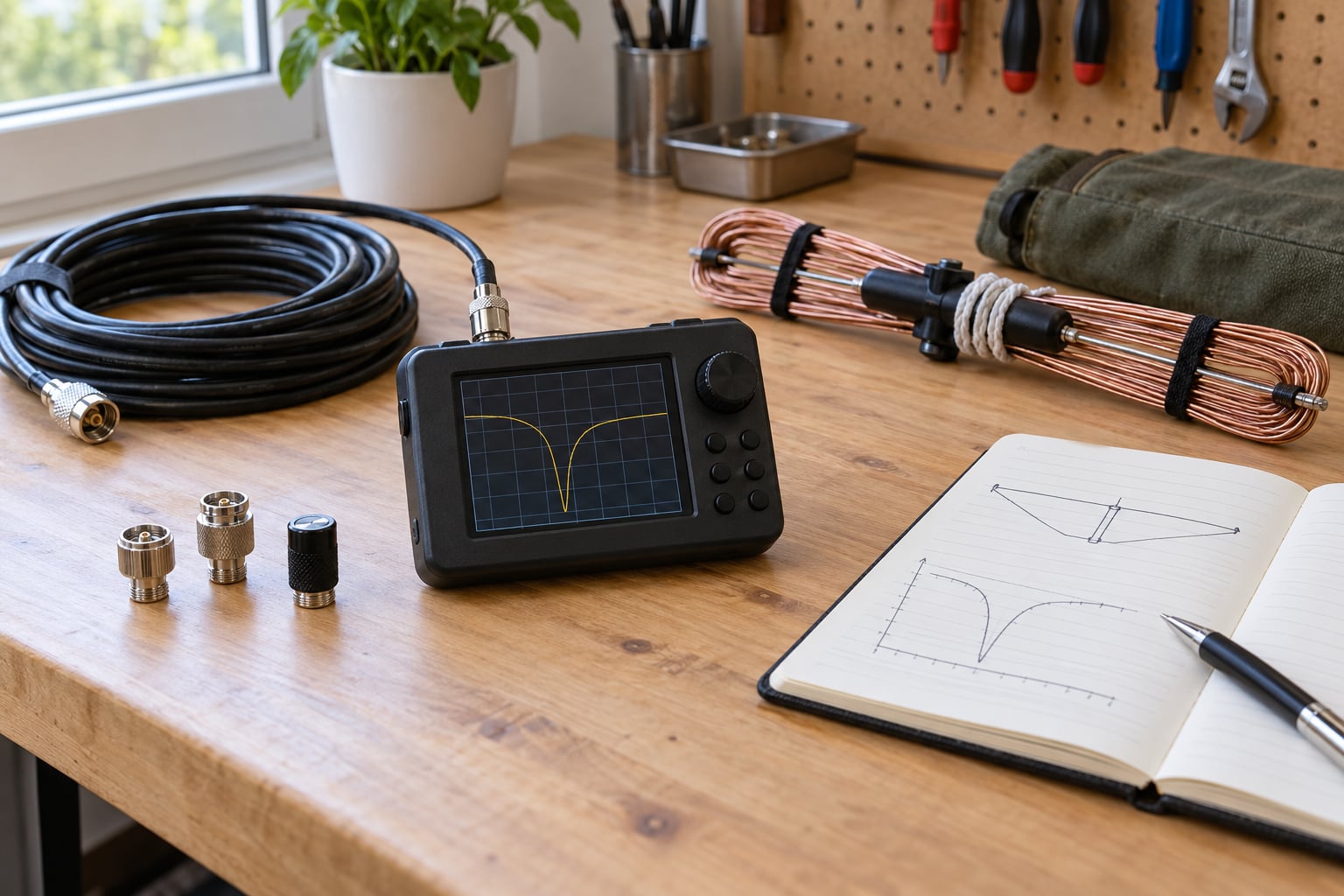
You measure SWR with a cheap antenna analyzer by setting the sweep range first, calibrating with the open, short and load standards, then connecting the antenna and reading the lowest point on the SWR curve. A pocket vector network analyzer — almost always a NanoVNA or a clone of one — does all of this at the push of a button, without putting your radio on the air.
The whole job takes about ten minutes once you have done it a few times, and the first attempt usually takes twenty because you recalibrate a lot. What matters is discipline: the same span on every run, the same calibration, the same cable position, and a known 50-ohm load at the start to prove the analyzer itself is behaving.
Table of Contents
- 1Quick answer: the measurement in ten steps
- 2What You Need
- 3Step-by-Step: How to Measure SWR with a Cheap Antenna Analyzer
- 4How to Set the Analyzer Frequency Correctly
- 5How to Read the SWR and Impedance Results
- 6How to Test the Same Antenna More Than Once
- 7What SWR Result Is Acceptable?
- 8How to Confirm Your Cheap Analyzer Is Telling the Truth
- 9Common Mistakes
- 10Frequently Asked Questions
- 11Can a cheap antenna analyzer measure SWR accurately?
- 12What is a good SWR reading for a handheld radio antenna?
- 13Do I need a dummy load to measure SWR with an antenna analyzer?
- 14Why does my antenna analyzer show high SWR at one frequency but low SWR nearby?
- 15Is impedance the same as SWR?
- 16Can I use an antenna analyzer while the radio is transmitting?
Quick answer: the measurement in ten steps
- Disconnect the antenna from the transmitter and discharge any static on the feedline.
- Set the sweep span, for example 14.0 to 15.0 MHz.
- Leave the antenna disconnected while you calibrate.
- Attach the open standard to Port 1 (CH0) and save the open calibration.
- Attach the short standard to Port 1 and save the short calibration.
- Attach the 50-ohm load to Port 1 and save the load calibration.
- Verify by leaving the load fitted and confirming SWR stays near 1.0:1.
- Fit the antenna or a test load to Port 1.
- Select the SWR trace and place the marker on the minimum.
- Write down the frequency of that minimum, the SWR there, and the R + jX.
What You Need
The analyzer itself is the only expensive part, and the cheap ones are genuinely usable for HF and VHF work. What people forget is the small pile of accessories that make a cheap unit trustworthy.
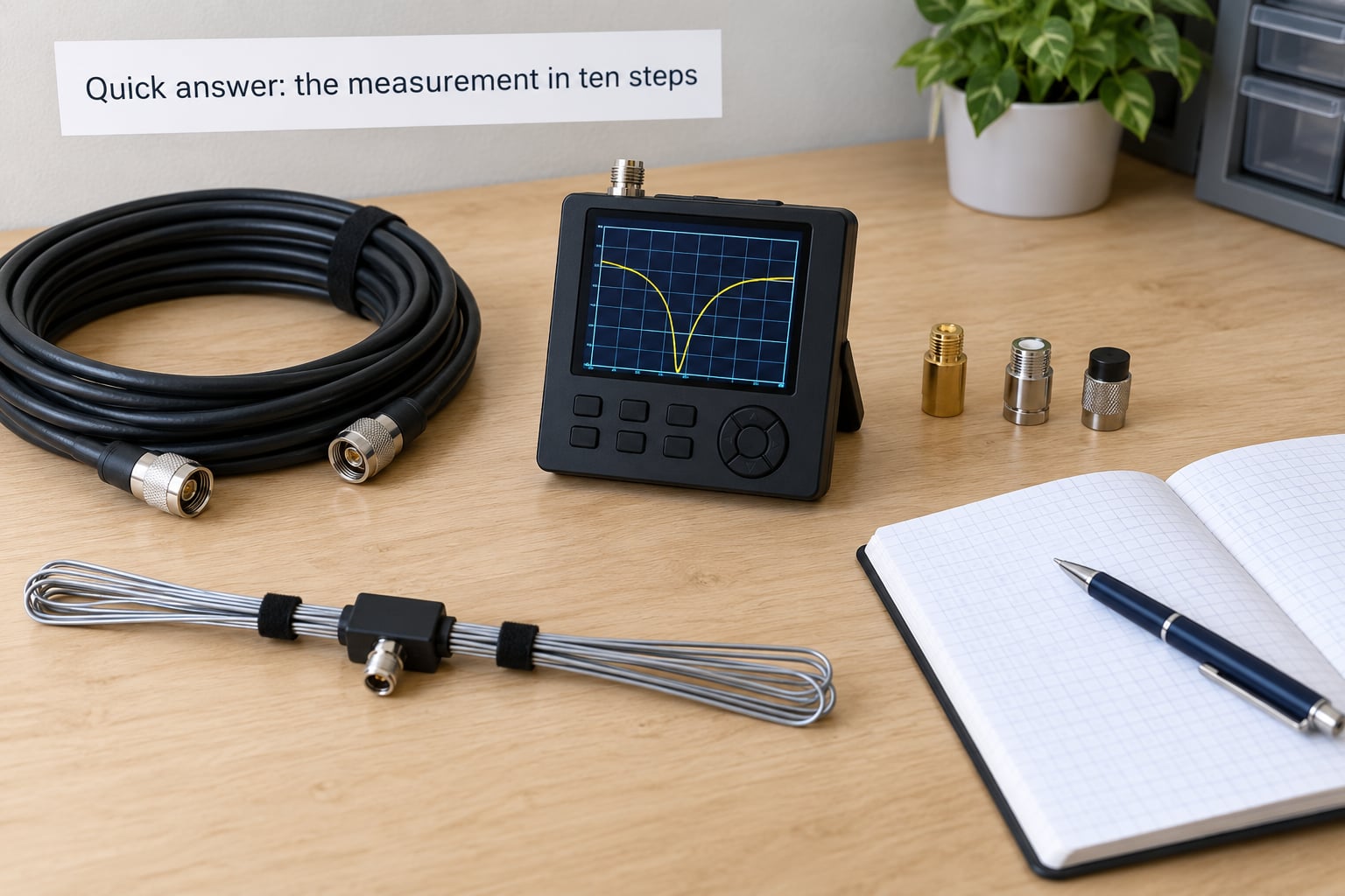
- An antenna analyzer. A pocket vector network analyzer with a one-port measurement (Port 1, labelled CH0 on most units). Two-port units also measure through transmission on CH1, which is how you measure feedline loss.
- A calibration kit. Open, short and load standards, usually gold-plated and barrel-shaped. Some kits include a small PCF or SMA female-to-SMA female adapter — treat that as a pass-through, not a standard.
- Adapters. Whatever converts the analyzer connector to your antenna connector: SO-239 to N-type, SMA female to SO-239, BNC to N, and so on. Write down which adapters were fitted at calibration, because each one sits between the calibration plane and the antenna.
- A short jumper. A 20 to 30 cm length of the same coax you plan to use. Long, lossy coax thrown on a desk is the single most common source of repeatable-but-wrong readings.
- A known 50-ohm termination. The load from the calibration kit is enough. A 50-ohm dummy load with an N connector is a useful second opinion.
- Basic hand tools. Small wrench, wire cutters, a tape measure, and side cutters for trimming antenna wire. Soldering iron and heat shrink if the feedpoint needs work.
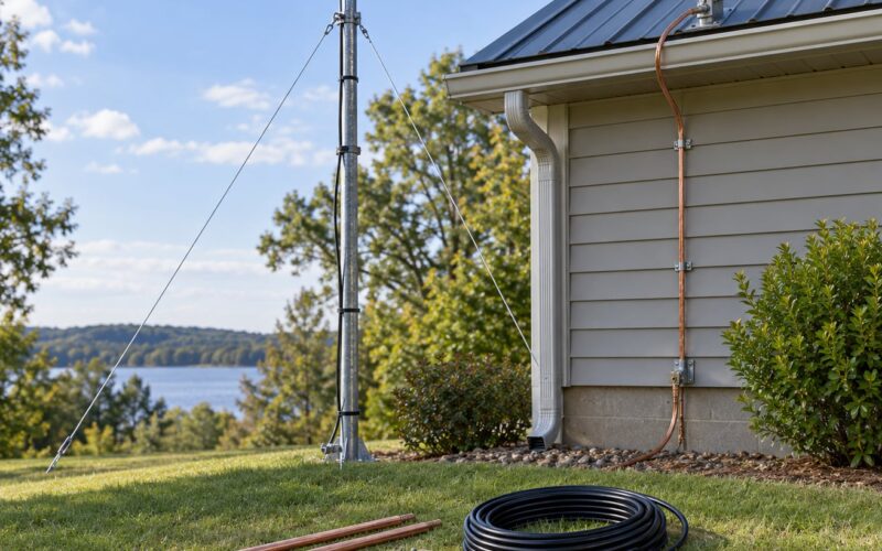
You also need to think about the radio side of the setup. Never measure with the feedline still connected to a transmitter, even a powered-down one. RF output transistors fail when they see a high reverse voltage, and a cheap analyzer is not a protective device.
If the feedline ran outdoors before the measurement, discharge it first. A long coax run picks up charge, and that charge will find its way through the analyzer. A resistor of a few hundred ohms across the feedline centre conductor and shield, or a screwdriver held across both after grounding the shield, does the job. If you like, clip the shield to a ground before you touch the centre.
Step-by-Step: How to Measure SWR with a Cheap Antenna Analyzer
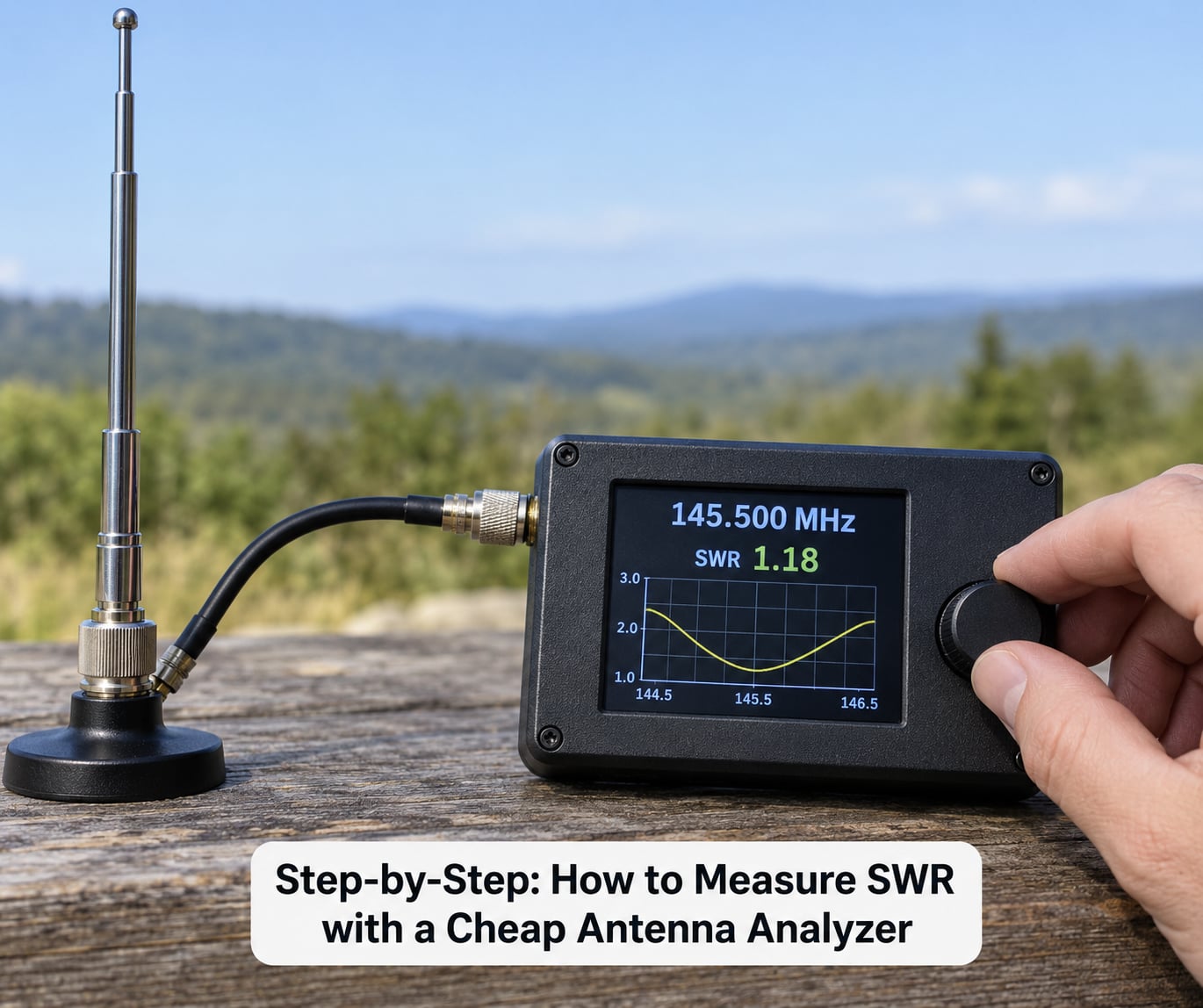
Work through this in the same order every time. Repeatability is what turns a single reading into a measurement you can trust, and repeatability comes from doing the same steps in the same sequence.
1. Set the sweep span before anything else. Decide the band you care about and set the start and stop frequencies so the band sits comfortably in the middle of the screen. For 20 metres that usually means roughly 14.0 to 15.0 MHz. Narrow spans give finer frequency resolution and a sharper dip; very wide sweeps across several bands on one screen make the dip small and hard to place a marker on.
2. Keep the antenna off the analyzer. Calibration happens with three known standards and nothing else attached. If the antenna stays connected, the open and short steps describe the antenna, not the analyzer.
3. Open, short, load, in that order. Screw the open standard firmly onto Port 1, then in the menu choose open calibration (usually CAL, OPEN). Repeat with the short standard, then with the 50-ohm load, saving load last. Each step tells the analyzer what the port actually looked like to a known standard, and it subtracts the error introduced by the cable and every adapter you fitted.
4. Verify before you trust. Leave the 50-ohm load fitted and look at the SWR trace. A healthy analyzer shows a flat line sitting close to 1.0:1 across the entire sweep. If it shows 1.4:1 on a known load, stop there and find out why — the load, the connector, or the analyzer. More on this in a moment.
5. Connect the thing you actually care about. Swap the load for the adapter and antenna, or for the feedline you want to characterise. Finger-tight is fine for SMA and for the brass thread on most clones; a light wrench touch is right for SO-239 and N-type. Do not crank a finger-tight connector with pliers, because a crushed centre pin produces a reading you will chase for an afternoon.
6. Pick the SWR trace and find the minimum. Most screens offer several traces at once, commonly S11 LogMag, return loss and SWR. Select SWR, then use the minimum-search function or drag the marker to the lowest point on the curve. Read off three numbers: the frequency at the dip, the SWR at the dip, and the impedance (R + jX) at the same marker position.
7. Look at the width of the dip, not just its depth. A narrow spike means the antenna is usable on one frequency and miserable on either side of it. A broad, shallow dip that still stays under your limit across the whole band is a better antenna than a needle-sharp 1.05:1 on a single frequency. Measure the bandwidth by finding the two points where SWR crosses your chosen limit, usually 2.0:1, and note the span between them.
8. Repeat the sweep twice. Watch the trace update. If it does not move, the reading is stable and you have a real number. If it wobbles, you have a connection problem, not an antenna problem.
9. Change something small and watch. Touch the coax near the antenna connector, then let go, then repeat. A reading that shifts noticeably when you touch the cable is telling you the outer shield is part of the antenna. On a handheld or whip setup that is normal and useful information; on a bench dipole it usually means your ground reference is not what you thought.
10. Write it down. Date, antenna, span, adapters used, dip frequency, minimum SWR, R and X, and the location. Six lines is enough. When the antenna comes down in six months and you want to know whether it was always this way, that log is the only answer you will have.
How to Set the Analyzer Frequency Correctly
Most beginner mistakes start with frequency, not with hardware. You are not tuning the radio channel — you are telling the analyzer which slice of spectrum to sweep, and where to put the marker inside that slice.
Set the span so your band of interest fills the middle of the screen with room on both sides. Then set the centre frequency to the middle of the band you intend to operate. If your plan is to work 14.200 to 14.350 MHz, a span of 14.0 to 15.0 MHz puts your marker in the correct region with better resolution than a 13 to 16 MHz sweep would.
Calibration is span-dependent on most units. Calibrating for 14.0 to 15.0 MHz and then sweeping 28 to 30 MHz gives you a trace that is not calibrated in that range, and it can look smooth while being wrong. If you work several distant bands, calibrate again for each one. Owners on the NanoVNA user group describe recalibrating every time they change the span as the single habit that fixed most of their odd readings.
Watch the frequency readout itself, not just the span fields. Cheap clones have been known to display a centre frequency that differs from the requested one, especially near the edges of their usable range. Confirm the displayed number matches what you asked for before you trust a marker position.
How to Read the SWR and Impedance Results
SWR is a single number: the ratio of forward to reflected wave on a line. Impedance is a pair of numbers, written as R + jX. R is resistance in ohms, X is reactance in ohms, and the j just means the second value is imaginary.
What you are really looking for is a dip in SWR near a frequency where X is close to zero and R is close to 50 ohms. Those three facts together tell you the antenna is resonant, and they tell you whether it is resonant the right way for your system.
| Reading | What it means | What to do |
|---|---|---|
| X positive, dip low in frequency | The antenna is electrically too long — inductive reactance | Shorten it. Every 1 percent of length is about 0.5 percent of frequency, so a 14.2 MHz dipole that dips at 13.8 MHz needs roughly 2.8 percent less wire |
| X negative, dip high in frequency | The antenna is electrically too short — capacitive reactance | Add length. Move the marker, calculate, then trim a few millimetres and re-measure |
| X near zero but R far from 50 | Resonant at the wrong impedance — a common fault in shrunken dipoles | Check element length and spacing before you chase the SWR number |
| No dip anywhere in the span | Not resonant in this range, or a bad connection, or a broken element | Widen the span once to confirm, then check connectors and continuity |
| SWR near 1.0:1 that never moves | You are probably looking at a load, not an antenna | Remove the load and re-sweep; a perfectly flat trace is a warning sign |
An analyzer proves what the antenna looks like at its feedpoint at the moment of measurement. It cannot tell you how the antenna behaves 30 feet in the air next to a chimney, whether it radiates well, or what your coax does on the way to the shack. Those need either a comparison against a known-good reference or a second measurement in place.
Return loss and S11 are the same information in different clothing. Return loss is measured in decibels and larger is better; S11 LogMag is the magnitude of the reflection coefficient, smaller is better. A return loss of 20 dB and an SWR of 1.2:1 describe the same match. Most screens show all three, and you can use whichever one you find easiest to read.
How to Test the Same Antenna More Than Once
One measurement is a reading. Three identical measurements are a result. The difference matters because cheap analyzers are sensitive to temperature, battery voltage, cable position and nearby metal, and because your own body is a large conductor sitting near a low-bandwidth antenna.
Here is the repeat protocol I would use. Keep the antenna in exactly the same place, do not move the desk, and keep the coax draped the same way — not pinched under a textbook, because a pinch changes the cable’s characteristic impedance slightly and can introduce common-mode current. Run the sweep three times and note the dip frequency and minimum SWR each time. If all three agree, the reading is real.
Then run a deliberate touch test. Put a hand on the antenna or the connector, sweep again, and compare. If the number changes by more than the repeat spread, the antenna needs a counterpoise or a proper ground reference, or the shield is doing part of the radiating. That is not an error in the measurement; it is the measurement telling you something about the installation.
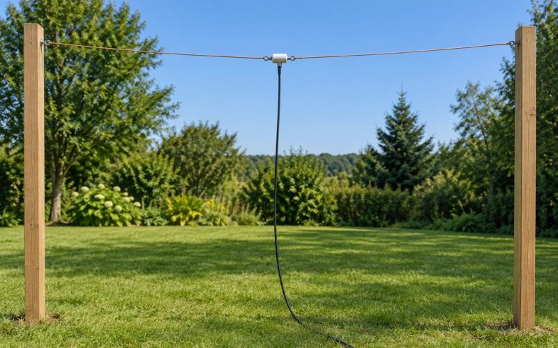
Outdoors, repeat with the antenna in its final position. The same dipole on a bench and at the top of a mast rarely share a dip frequency, because the ground plane and nearby objects shift the resonance. A reading taken before mounting is useful for setting length; the reading that matters is the one from the installed position.
Keep a short log and re-run it after storms, after nearby construction, and whenever the transmitter reports high SWR. SWR is not a one-time property of an antenna, which is a point that comes up constantly on radio forums and rarely appears in print guides.
What SWR Result Is Acceptable?
For US amateur radio work, 1.5:1 or better across the band you want to operate is comfortable, 2.0:1 is the usual ceiling for a homebrew antenna, and 3.0:1 or more means stop and find the fault rather than transmit into it.
| SWR | Reflected power | Typical reading | Recommended action |
|---|---|---|---|
| 1.0:1 | 0 percent | A perfect match, rare on a real antenna | Check you are not measuring a 50-ohm load |
| 1.5:1 | About 4 percent | Excellent | Nothing to fix; you are done |
| 2.0:1 | About 11 percent | Acceptable for most HF work | Usable, but look at bandwidth and location |
| 2.5:1 | About 18 percent | Workable on modern radios | Worth investigating before long transmissions |
| 3.0:1 and above | 25 percent and up | Poor | Find the fault: connectors, feedline, element length, environment |
None of these numbers tells you how much signal leaves the antenna. A well-matched antenna in a bad location radiates poorly, and a modest match on a rooftop with clear ground plane can outperform a beautiful 1.1:1 sitting in a shed. SWR is a mismatch measurement, not a radiation measurement. What it does do reliably is keep your transmitter from working against a load it cannot drive.
Low coax loss flatters the reading, and this is where most confusion starts. If you measure through 30 metres of lossy feedline, the loss plus any mismatch can drag the reading toward 1.0:1 even when the antenna itself is a poor match. The loss is not reducing the mismatch; it is disguising it. Measure at the feedpoint for the truth about the antenna, and measure at the radio end for the truth about your system.
| Where you calibrate | What the reading tells you | Use it for |
|---|---|---|
| At the analyzer connector | Everything beyond that connector, including adapters and cable | Bench work on the antenna itself |
| At the end of a short jumper | The antenna, jumper and adapters cancelled out | Quick checks of whips and stub antennas |
| At the antenna feedpoint | The antenna alone, with all cable and adapters cancelled | Judging whether the antenna design is good |
| At the radio end of the feedline | The whole system as the transmitter will see it | Troubleshooting what your radio reports |
Whichever plane you pick, stay on it and write it in your log. Switching planes between a bench run and an installed run is a common reason two people measure the same antenna and get different answers.
How to Confirm Your Cheap Analyzer Is Telling the Truth
Checking the tool itself takes two minutes, and most guides skip it. Fit the 50-ohm load to Port 1, sweep a range you care about, and look at the SWR trace. A working analyzer shows a flat line sitting near 1.0:1 across the whole span.
Then fit the short standard. The trace should collapse to near 1.0:1 at essentially every frequency, and the impedance should read close to zero ohms. Fit the open and it should read very high impedance. If those three checks pass and the load check fails, the problem is in the load, the connector, or the analyzer’s front end.
Cheap clones vary a lot in quality, and owners report drift over time, especially toward the top of the frequency range. A unit that reads a clean 1.05:1 on the load today and 1.6:1 next month has drifted, and recalibrating will not fix a drifting instrument. Make the load check part of your routine — once at the start of a session is enough. If a band still looks wrong after a fresh calibration, repeat the load check on that band specifically.
Common Mistakes
Almost every bad SWR reading traces back to one of a handful of causes. Work down this table before you start trimming wire.
| Symptom | Likely cause | Fix |
|---|---|---|
| Reading changes when you touch the cable | Common-mode current on the shield, or an ungrounded antenna | Fit a proper counterpoise, keep hands off the coax, use a ferrite choke if needed |
| SWR is impossibly good, around 1.0:1 everywhere | Measuring a load or a short cable, not the antenna | Remove the load and sweep again; a flat trace means nothing is attached |
| Trace is smooth but wrong everywhere | Calibrated on one span, sweeping another | Recalibrate for the span you are using |
| No dip anywhere in the span | Antenna not resonant here, or a broken element | Widen the span once, then check continuity and connector tightness |
| Reading shifts when the coax is moved | Coax pinched or lying on a metal surface | Reroute the cable, lift it off the bench, keep the same position for repeat runs |
| Works on the bench, poor up on the mast | Different environment, and the bench reading was never the real one | Measure in the installed position and re-tune there |
| Radio reports high SWR, analyzer reports fine | Radio’s internal SWR meter is approximate, or the feedline is lossy | Trust the analyzer reading at the feedpoint, then check feedline loss with two ports |
| Reading changes between visits | Temperature, a nearby vehicle, or a loose connector | Torque the connectors, log the conditions, re-measure in the same setup |
Two mistakes deserve their own paragraph because they are so common. The first is measuring indoors and trusting the number. Walls, a metal desk, a window frame, a laptop and your own body all sit close enough to a half-wave dipole at 14 MHz to move the resonance by hundreds of kilohertz. An indoor reading is still useful for setting relative length; it is not the number you will get outside.
The second is changing the antenna and keeping the old reading. If you shorten an element, the sweep must be re-run. The trace updates live, but a marker left at the old frequency will keep reporting a number for a dip that has moved. Put the marker back on the minimum every time.
Two more habits close out the list. Never trim a dipole until the reactance sign tells you which way to go — the common advice on ham forums is to fold the wire back on itself and twist it rather than cutting, because you cannot put length back onto a wire that has already been trimmed. And never treat a good SWR as proof of a good antenna, which is the counter-intuitive point that catches out almost everyone new to this.
Frequently Asked Questions
Can a cheap antenna analyzer measure SWR accurately?
Yes, for most purposes. A pocket vector network analyzer can give you a repeatable SWR figure, a dip frequency and a full R plus jX readout without transmitting, which is more than an in-line SWR meter gives you. Its limits are accuracy at the very top of its frequency range, drift over months, and sensitivity to how you handle the cable and your body. Confirm yours by sweeping a known 50-ohm load and checking the trace stays flat near 1.0:1.
What is a good SWR reading for a handheld radio antenna?
Under 2.0:1 at your operating frequency is usable, and under 1.5:1 is comfortable. Real handheld rubber duck antennas often measure far worse than that, commonly 3:1 or more, because they are heavily shrunk and heavily loaded by the body and the radio chassis. That is normal rather than a fault. Shortening the antenna raises the resonant frequency and lowers the reading, but the installed reading will not match your bench reading once you put it back on the set.
Do I need a dummy load to measure SWR with an antenna analyzer?
You need a 50-ohm load, and the one in your calibration kit is exactly that. It serves two purposes: it is one of the three calibration standards, and it is the reference you sweep against to confirm the analyzer is working correctly. A separate dummy load is useful for testing transmitter output and as a second opinion on a suspect antenna, but you do not need one to measure SWR or to tune an antenna.
Why does my antenna analyzer show high SWR at one frequency but low SWR nearby?
Because that dip is your antenna’s resonance. A resonant antenna absorbs energy instead of reflecting it, so the mismatch falls away around one particular frequency and rises again on either side. The shape of the dip tells you about bandwidth: a wide dip means the antenna works across a wide range of frequencies, a narrow spike means it is usable on one and poor near it. If the dip sits lower than your band, the antenna is too long; if higher, too short.
Is impedance the same as SWR?
No, and the distinction matters. SWR is a single ratio derived from how much reflected energy comes back. Impedance is the antenna’s actual electrical characteristic, written as R plus jX in ohms. An antenna can show a great SWR and an impedance far from 50 ohms if feedline loss is hiding the mismatch, so measure impedance at the feedpoint when you care about the antenna itself, and use SWR for the quick pass or fail check.
Can I use an antenna analyzer while the radio is transmitting?
No, and this one is not a matter of preference. Disconnect the feedline from the transmitter before you connect the analyzer. Output devices fail when they see a high reverse voltage from a high reflected load, and the analyzer adds nothing that would protect them. A cheap analyzer is also not isolated from the antenna in any way that matters. Transmit first with your own meter if you need to, then power the radio down and disconnect it before you measure.
Start with the ten steps above and do not skip the verification load. Confirm the analyzer reads close to 1.0:1 on a known 50-ohm termination, calibrate at the reference plane you intend to use, and sweep your antenna three times before you accept any number. Once that habit is in place, how to measure SWR with a cheap antenna analyzer stops being a guessing game and becomes something you can repeat on every antenna in your shack, plus the handheld in your pocket.