Grounding a ham radio antenna safely means bonding the mast or tower, the antenna, the coax shield and your station equipment into one system that shares the building’s service entrance ground. You do that by driving copper ground electrodes, bonding every metal part to them with solid copper conductors, putting listed surge protection on the feed line at its entry point, and wiring your shack to a single ground bus. Start by planning the whole layout before you drive a single rod.
This guide is US-focused and built around the National Electrical Code (NFPA 70), mainly Articles 250, 800 and 810. Numbers I give for rod length, spacing, conductor gauge and resistance targets are rules of thumb drawn from common practice and standards like IEEE Std 81, not code requirements. Where the work crosses into your service panel, your utility or a climb up a tower, it is a job for a licensed electrician.
Never disconnect, lift or omit a required protective earth, bonding conductor or surge device to change noise or SWR. That conductor is a life-safety system, not an operating knob. An unbonded station ground can make storm damage worse, because surge current that had a short path to earth gets routed through your coax, control cables and house wiring instead.
Table of Contents
- 1What You Need
- 2Step-by-Step: How to Ground a Ham Radio Antenna System Safely
- 3Plan the Grounding and Bonding System
- 4Choose Code-Compliant Grounding Electrodes
- 5Bond the Antenna, Mast, and Coax Shield
- 6Install Surge Protection and Entry Protection
- 7Test, Inspect, and Document the Installation
- 8Common Mistakes
- 9Frequently Asked Questions
- 10Does a ham radio antenna need to be grounded?
- 11How should a radio tower be grounded?
- 12Do I need to ground my coax?
- 13Can I use a water pipe as a ground for my radio?
- 14When should I call an electrician for antenna grounding?
- 15Conclusion
What You Need
Most of the cost of a grounding system is copper and the electrician’s half of a day, not exotic hardware. Gather everything before you start digging.
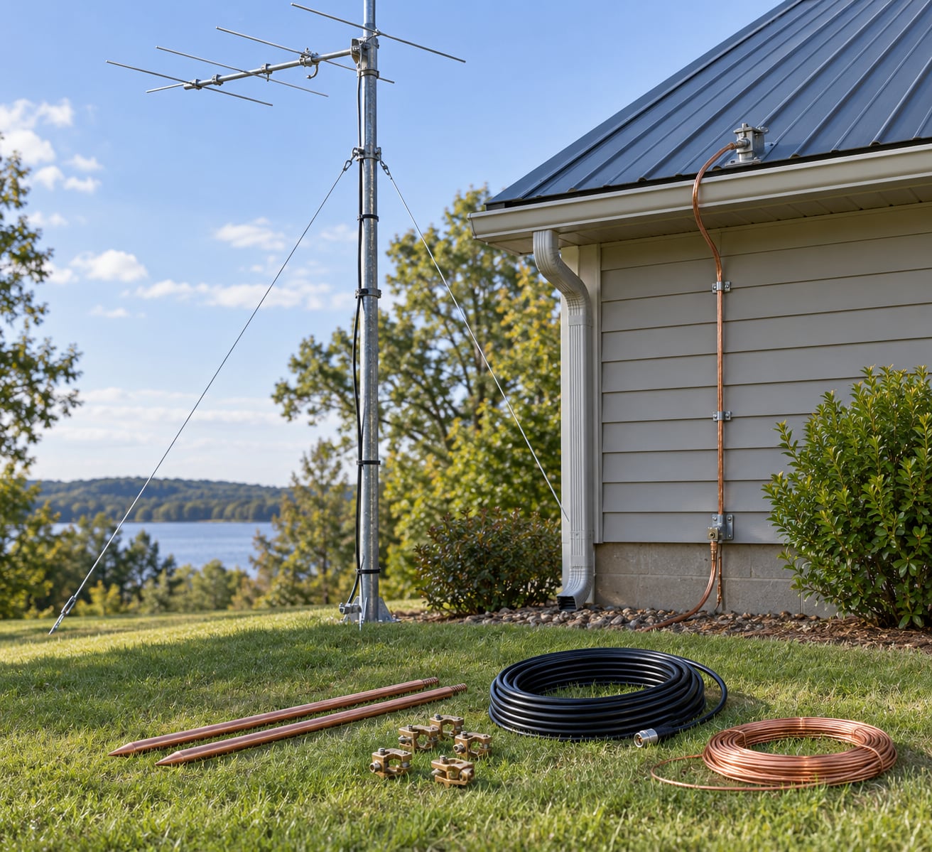
- Ground electrodes. Copper-clad or solid copper rods, typically 8 ft or longer, or copper pipe electrodes. Match them to the equipment manual and to what your soil allows.
- Bonding conductors. Solid bare copper is the usual choice for surge and safety bonds. Braid works for flexibility but is discouraged for RF purposes, where surface area matters more than you would think.
- Connectors. Mechanical ground clamps, split-bolt connectors, or exothermic welds. Bolts alone loosen; torque is not the long-term answer.
- Copper strap or flashing. Wide copper for bonding chassis, rotator frames and tower legs where a round wire cannot make good contact on flat or painted metal.
- Ground bus hardware. A copper ground bus bar for the shack, plus a short heavy strap from the bus to the building ground.
- Listed feed-line surge protection. A coaxial protective device with a proper bond to the shield and a ground lead, installed at the point where the cable enters the building.
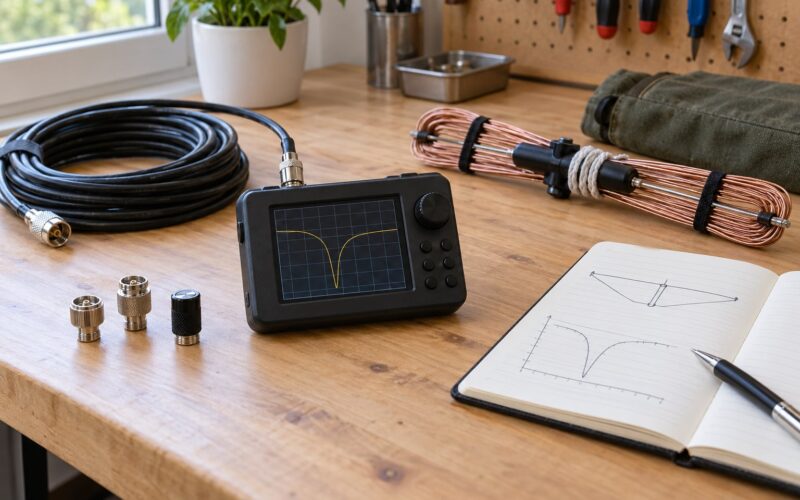
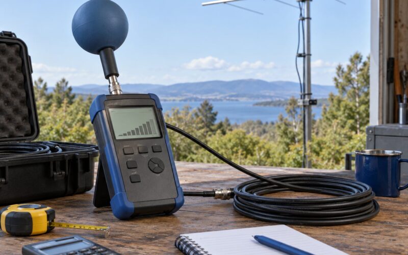
- Measurement gear. A low-resistance ohmmeter for continuity and bond checks, and, if you want an earth resistance number, a ground resistance tester or a clamp-on ground meter.
- Documentation. The station equipment manual, any applicable local electrical requirements, and something to draw a run map on before the trenches and planters get dug.
- Safety gear. Gloves, eye protection, and a plan for dealing with power at the panel. If the panel is involved, you are in licensed-electrician territory.
Two of those jobs are genuinely different from the rest and worth naming separately. Low-voltage RF grounding is about giving your antenna and feed line a return path so they stop behaving like extra antenna. Electrical and lightning-protection grounding is about life safety, fault current and steering surge current into earth through conductors big enough to carry it. Mixing the two specifications is where most amateur mistakes live.
Step-by-Step: How to Ground a Ham Radio Antenna System Safely
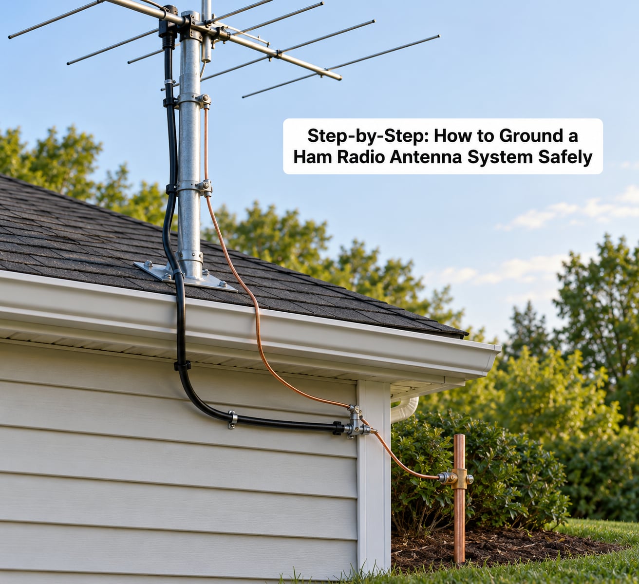
The order matters more than the individual connections. Work from the plan outward to the electrodes, then inward to the shack, then verify.
Plan the Grounding and Bonding System
Draw every metal object that could carry current before you buy anything: the antenna elements and boom, the mast or tower legs, the coax shield, the rotator and its control cable, any metal roof or siding you clamp to, the shack equipment, the power branch circuit, the service entrance, and any telephone or data cable entering the house.
The design goal is a single bonded system with one deliberate entry point. Power, coax, control cable and any telco or network cable should enter through a single bulkhead or entrance panel, bonded together at that point, with a heavy strap running to the shack bus. That is the layout experienced operators describe working, and it is far easier to build into a new station than to retrofit.
Decide now whether this is a professional job. Call a licensed electrician if you will touch the service panel or the grounding electrode conductor, if your local authority requires a permit or inspection, if the run has to cross a utility easement, or if the tower work involves climbing above what you are comfortable on. Lightning-protection design is a specialty too: a surge protection system has to be coordinated from air termination down to earth terminals, and a part-installed one is not protection.
Choose Code-Compliant Grounding Electrodes
Ground rods handle surge and lightning current. Copper-clad rods are the common choice because they drive easily and corrode slowly; copper pipe electrodes are used where rod driving is impractical, such as shallow rocky soil. Length is where the folklore starts, so be clear about it: 8 ft is a rule of thumb, not a magic number, and depth is only one variable.
Soil matters as much as depth. In sandy or rocky ground, resistance stays high no matter how many feet you bury, and the practical move is multiple electrodes spread out and bonded together rather than one deep rod. Keep spacing between electrodes on the order of ten times the rod length, and keep the array as close to what it protects as you can manage.
Your best electrode is often one you already have. The building grounding electrode system is the right place to land, because that is the electrode the electrical safety system already relies on. The service entrance bonding point is where the grounding electrode conductor from the panel meets it, and in most homes a run to that point is the single most valuable thing you can do for surge protection. Metal utility systems such as well casings, water service piping and the utility’s own grounding conductors can be part of the system under code, but the pipe has to be bonded at the service entrance, and you must confirm suitability with the utility before relying on anything. Paint, corrosion and plastic inserts make improvised clamps useless.
Whichever route you take, follow your radio equipment manual, the manufacturer’s installation instructions, the National Electrical Code and whatever your local authority requires. When those disagree, your radio equipment manual and the local authority win over anything you read on a forum, including this page.
Bond the Antenna, Mast, and Coax Shield
Start at the tower. Each leg or the mast itself gets its own approved bonding conductor down to the electrode array, bonded with mechanical clamps or exothermic welds, using wide copper strap where the surface is flat or painted. One conductor shared between two legs is not a second bond; it is a chattel.
Bond the coax shield at the tower base, where the shield current wants to go, and again at the entry point inside the house. Where the shield is grounded at both ends, the path has to be short and heavy, otherwise the coax itself becomes the current path and you are back to square one. Bonding rotator control cables and any other shield-bearing line follows the same logic, for the same reason.
Daisy chaining is the failure mode to avoid. Running a separate wire from each device to a separate rod sounds like it eliminates ground loops, and it does the opposite: you end up with several slightly different potentials, current that takes the long way round through your equipment, and a storm path through the building. Bond everything to one common point at the bus, and do not trust a bolt that has not been torqued and will not be checked again. Clean the metal before you clamp, and expect to look at these connections every couple of years.
Install Surge Protection and Entry Protection
Feed-line protection goes where the coax enters the building, in the same enclosure as the power and telco entries, with the ground lead kept short and bond to the same point as the entrance. That gives surge current a path to earth that does not run through your equipment. Mounting it at the shack instead leaves the entire outdoor cable run unprotected, which is most of the cable.
Use a device listed for the service and rated for the coax type in use, and connect the shield bond to the enclosure, not just to the connector shell. Keep the ground lead as short and straight as you can; every extra inch of twisting adds inductance at the frequencies surge energy actually lives at.
Two substitutions get refused every time. A household power strip is not antenna surge protection, and it does nothing at all for a strike or an induced surge on the coax. And you never tie unrelated wiring together because it seemed convenient: control cables, telco pairs and unrelated circuits each need their own protection and their own bonding, handled as what they are.
Test, Inspect, and Document the Installation
Start with continuity. With the system de-energized and equipment disconnected, verify that every intended bond actually measures low resistance end to end, and that you have not accidentally created a daisy chain you did not intend. Check each clamp for corrosion, looseness and clean metal contact, and check that no conductor runs through a wet area, across a walkway, or where a mower or future landscaping will find it.
Then measure earth resistance if you care about the number, using a ground resistance tester or a clamp-on meter around the grounding electrode conductor. What a low reading proves is narrow: that your electrode system presents low resistance to earth. It does not prove the bonds are all solid, that the conductors are correctly sized, or that touch and step potential at the array is acceptable. An RF measurement of your ground run tells you about common-mode behavior on the feed line. Neither one substitutes for a visual inspection of the hardware.
Finish by checking station performance. RF in the shack, a warm coax jacket, an unexpected SWR change or a mic that bites at high power all point at common-mode current rather than at a grounding defect, so treat those as symptoms to diagnose, not as evidence the ground is wrong.
Write down the layout and file it somewhere you will find in ten years. Operators who map their ground system tell you they stopped fearing landscaping surprises; operators who do not are the ones who find out later.
Common Mistakes
Most amateur grounding errors come from trying to solve one problem with a tool built for another. The fixes are mostly about deleting something rather than adding it.
- Treating RF ground and electrical safety ground as the same thing. An RF return run is short, thick and sometimes solid; a safety and surge bond is sized and routed for fault and surge current. Fix: decide which job each conductor is doing before you cut it.
- Installing random extra rods. A rod driven to satisfy a number, far from anything it protects, adds little and can create a separate potential you then have to bond back. Fix: bond rods together and tie the array to the building grounding electrode system.
- Bonding to plumbing without approval. A cold water line is not an electrical ground, and plastic inserts and corrosion make it unreliable. Fix: use the pipe only if code permits, bond it at the service entrance, and get the utility or an electrician involved.
- Daisy chaining and isolated grounds. Per-device wires to per-device rods create ground loops and push surge current through the house. Fix: one bonded system, one entry point, one bus.
- Ignoring corrosion. Aluminum-clad clamps on copper, bare copper in wet soil, and bolts that were never torqued properly all fail quietly. Fix: compatible metals, mechanical or exothermic connections, and periodic inspection.
- Routing conductors badly. Running a bonding conductor through a wet area, along a fascia where water sits, or across a path creates both a corrosion and a trip problem. Fix: route it straight, supported and away from standing water.
- Using undersized or unsuitable wire. Thin stranded wire and copper braid are not substitutes for a solid bonding conductor on a surge path. Fix: solid copper sized for the job, and keep braid for flexibility where it is genuinely needed.
- Believing grounding prevents strikes. It does not. Grounding and surge protection reduce what happens after a strike; nothing on your property changes where lightning goes. Fix: keep the expectation honest and the protection coordinated.
- Making unsafe roof or tower changes. Drilling a tripod into a roof, unclimbing a mast, or running a new rod next to buried services is not an antenna project. Fix: qualified help for structure, service panel and anything above the reach of a stable ladder.
One more that deserves its own line: unplugging the radio during a storm does not make an unbonded system safer. If surge current is already moving, isolation at the desk just means it arrives and dissipates somewhere else. Bonded entry protection is the answer.
Frequently Asked Questions
Does a ham radio antenna need to be grounded?
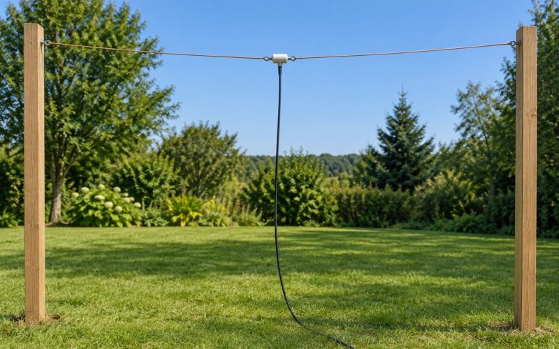
Yes, and the reason is safety rather than signal. A fixed antenna, its mast or tower, and its coax shield should all be bonded into a single system that ties back to the building grounding electrode system, so fault current and surge energy have a low-impedance path to earth. A balanced dipole is still bonded at its feed point and to any metal supports. A proper ground will not fix poor antenna design or raise your signal reports.
How should a radio tower be grounded?
Give every tower leg or the mast its own bonding conductor down to the electrode array, using approved mechanical clamps or exothermic welds and wide copper strap on flat or painted metal. Bond the coax shield at the tower base, then again at the building entry, and connect the array to the building grounding electrode system. Run the tower conductor to the service entrance bonding point where you can. Do not leave the tower as its own isolated system.
Do I need to ground my coax?
Ground the coax shield at the point where it enters the building, and again at the tower base, using a short heavy bond at each end so the shield is not carrying surge current on the way. A properly installed two-end shield bond actually reduces the voltage the feed line sees. Add listed coaxial surge protection in the same entrance enclosure as the power, with a short ground lead bonded to the same point.
Can I use a water pipe as a ground for my radio?
Sometimes, and only under code with conditions. Metal water service piping can be part of a grounding electrode system, but it must be bonded at the service entrance and installed metal, and plastic inserts or a dielectric section break it. Utility water grounds belong to the utility, and repiping may change what you have. Confirm suitability with your utility or a licensed electrician rather than assuming a clamp makes it a ground.
When should I call an electrician for antenna grounding?
Call one when the work touches your service panel or grounding electrode conductor, when a permit or inspection is required by your local authority, when new rods go near buried utility services or an easement, or when the tower is beyond safe ladder reach. Lightning-protection design is a specialty, and a partially installed surge system is not protection. Do the survey, the plan and the low-voltage work yourself, and leave the panel work to someone licensed for it.
Conclusion
Start with the plan, not the rod: list every metal part that could carry current, pick one entry point for power, coax and control cable, and confirm with your radio equipment manual and local authority what the installation must meet. Build outward to the electrodes and inward to a single shack bus, bond rather than isolate, and treat any required protective conductor as untouchable.
Then have a licensed electrician review anything touching the service panel, the grounding electrode conductor or the tower climb, install listed feed-line protection at the entry, and verify the finished system with continuity and bond checks before you transmit. Grounding done properly is what stands between a storm and a burned-out shack, and it has never once raised your signal reports.