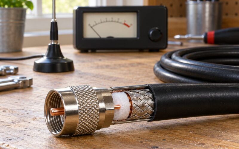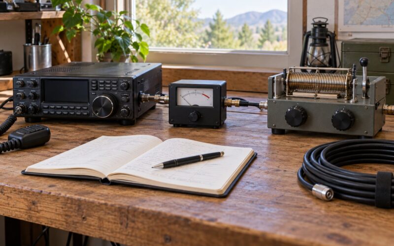
Learning how to install coax connectors without soldering mistakes is mostly about two things: stripping the cable to the right depth, and keeping the center conductor from ever touching the shield. Get those right and a crimp or compression connector gives you a joint that is mechanically as sound as a soldered one, and it takes about ten minutes per end with no heat and no burns. The whole job on a single RG6 or RG8X end is beginner-level, but the strip dimensions are exacting.
There is one rule that breaks everything else: the center conductor must never touch the braided shield. Touch means a dead short, zero signal, and on transmit a very expensive afternoon. Everything else in this guide is detail in service of keeping those two conductors apart.
I have made this mistake more than once, both on a TV feed and on a dipole feed point, and both times it was the same cause. On a TV run I stripped the jacket too long, the foam dielectric bulged, and when I pushed the connector on the foam rode up and the braid reached straight across to the center conductor. The set said no signal. On the dipole I was in a hurry, the braid was splayed from a dull knife, and one stray strand found the center pin.
Both failures took fifteen minutes to fix. That is the argument for practising on a short offcut before you touch a run that matters.
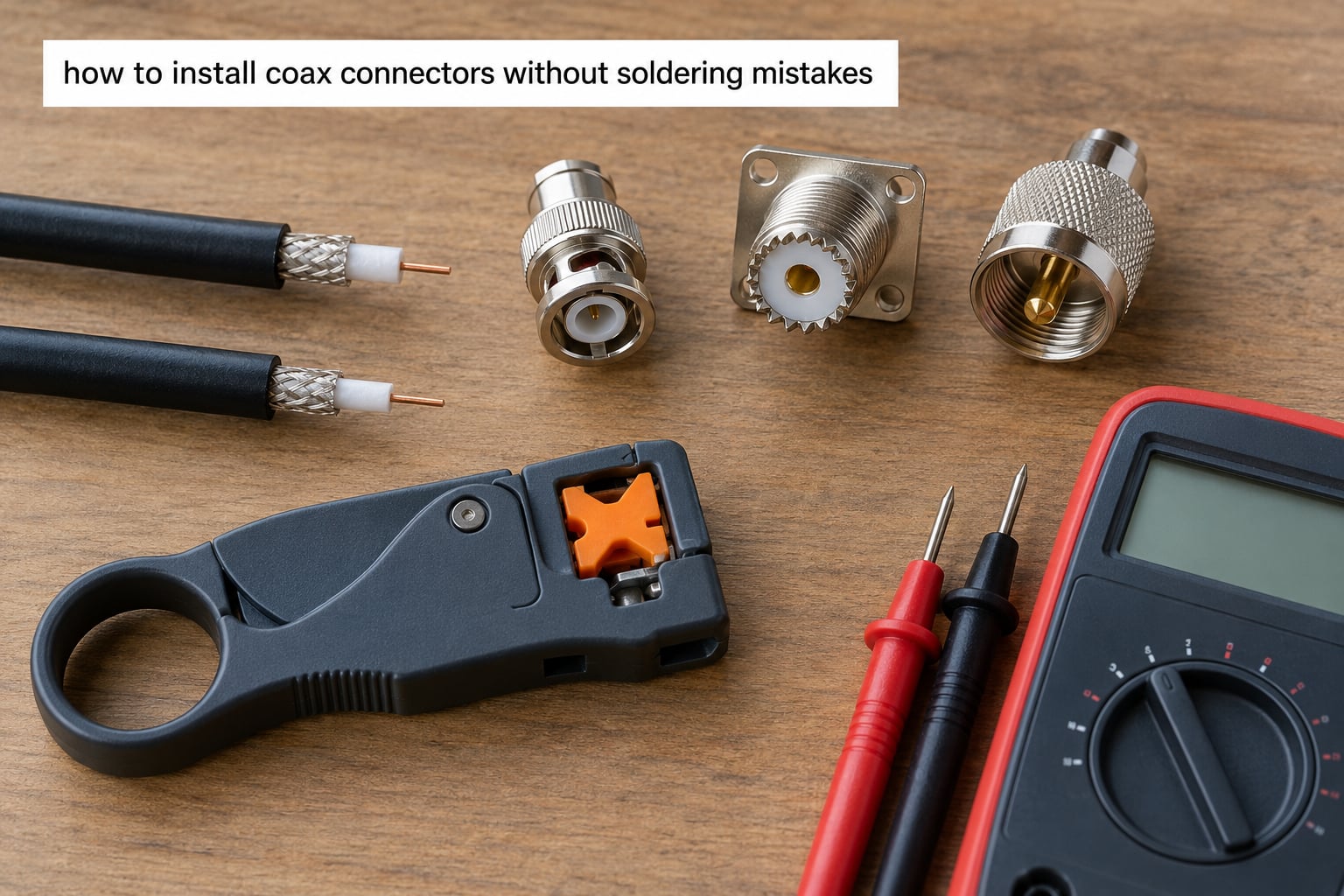
Table of Contents
- 1What You Need: Tools and Connector Types That Match Your Cable
- 2Which connector type suits which job?
- 3What stripper and crimper do you need for which cable?
- 4Step-by-Step: Strip, Terminate, Test
- 5How to install coax connectors without soldering mistakes: match, cut and strip cleanly
- 6Attach a solderless connector: crimp, compression or twist-on
- 7Solder a PL-259 or other soldered connector
- 8Test the completed connection before it goes outside
- 9Common Mistakes: Why Each One Fails and How to Fix It
- 10Symptom, likely cause and fix
- 11Frequently Asked Questions
- 12Is it better to solder or use a solderless coax connector?
- 13Why does my newly installed PL-259 connector show low resistance?
- 14Do RG-58 and RG-8X use the same BNC connector?
- 15How can I test a coax connector before installing it on an antenna?
- 16Can I learn how to install coax connectors without soldering mistakes on outdoor feedlines?
- 17Conclusion: Start With a Short Offcut and a Meter
What You Need: Tools and Connector Types That Match Your Cable
You need very little: a stripper, a matching connector, and the right tool for that connector type. The trap is almost never the technique. It is fitting a connector meant for a thinner cable onto thicker coax, or a stripper whose blades are set for a different gauge.
Start by identifying your cable. The jacket printing is the easiest read, but if it has worn off, measure the outer diameter with calipers or a ruler. RG59 is about 6.5 mm, RG6 about 7 mm, RG8X about 8.3 mm, and LMR-400 around 10.3 mm. A stripper with a numbered or lettered strip guide is far safer than a fixed-blade one, because the guide tells you where the blade will cut.
You also need a way to test what you have built. A multimeter on the continuity and resistance ranges is the bare minimum, and a cheap coax tester gives you a pass or fail in a second. Work on a clean, dry surface with good light. You are looking for a clean, even strip, and that is hard to judge in poor light.
Which connector type suits which job?
Connector types differ mainly in tools, permanence and where they belong. The table below is the honest comparison, including the methods that need nothing at all.
| Connector type | Tools needed | Skill level | Best for |
|---|---|---|---|
| Compression F | Stripper and compression tool | Easy | Permanent RG6 runs, TV, satellite, internet |
| Crimp-on F | Stripper and F crimper | Easy | RG6 where you already own a crimper |
| Twist-on F | Stripper only, or even bare pliers | Very easy | Test leads, temporary set-up, repairs in a hurry |
| Push-on F | Stripper only | Very easy | Quick hookups, but the contact is less reliable long term |
| Crimp-on PL-259 | Stripper and crimper with the right die | Moderate | Ham radio feedline, RG8X, RG213 |
| Solder-on PL-259 | Iron, solder, flux | Moderate | Where you want a permanent, repairable joint |
| BNC or N-type | Matching crimper or solder | Moderate | Ham radio, CB, marine VHF, CCTV camera runs |
| SMA | Solder or a dedicated crimp tool | Advanced | Thin coax, higher frequency work |
Two notes on the table. Twist-on and push-on are genuine no-tool options and they work, but the mechanical retention is weak, so they are for temporary work rather than a permanent rooftop run. SMA is the one entry where I would not hand a beginner a first project.
What stripper and crimper do you need for which cable?
Strippers, connectors and crimper dies must all match the same cable. A die sized for RG6 will crush an RG8X or LMR-400 connector, and a stripper set for RG59 will leave a thick RG6 jacket stopping the connector from seating. Use this as a cross-check before you start.
| Cable | Typical use | Matching connectors | Stripper guide to use |
|---|---|---|---|
| RG59 | Thin CCTV and older TV runs | F crimp, BNC, RCA | The RG59 slot, which is the thinnest |
| RG6 | TV, satellite, DOCSIS internet | Compression F, twist-on F, BNC | The RG6 slot |
| RG8X | Ham radio feedline | PL-259, SO-239, N-type | The RG8X slot if the stripper has one |
| LMR-400 | Higher power ham, CB and VHF | PL-259, N-type, BNC | Largest slot; never guess |
If your stripper has no slot for your cable, do not use a smaller slot and hope. Buy the matching stripper or use the knife method further down, which is slower but controlled.
Step-by-Step: Strip, Terminate, Test
The procedure runs in four parts: matching the connector and stripping the cable, attaching a solderless connector, soldering a PL-259 when that is what you have chosen, and testing the finished joint. Work in that order and check each stage before moving on. Testing before the joint goes outdoors is the difference between a five-minute fix and a stripped run.
How to install coax connectors without soldering mistakes: match, cut and strip cleanly
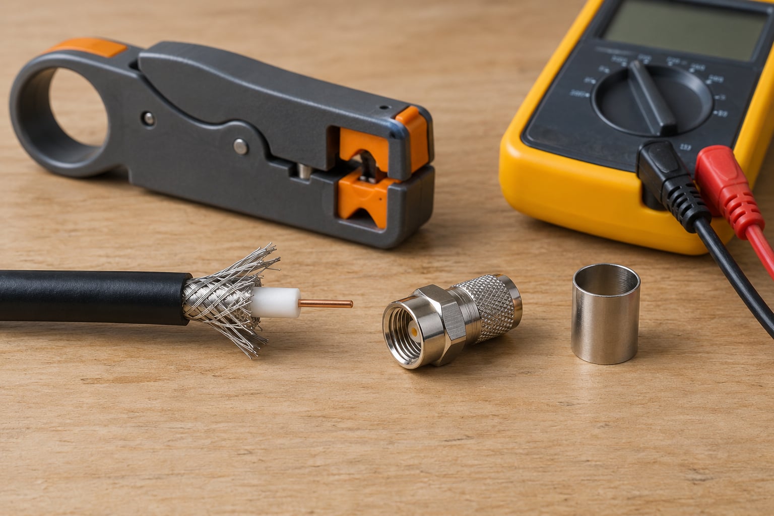
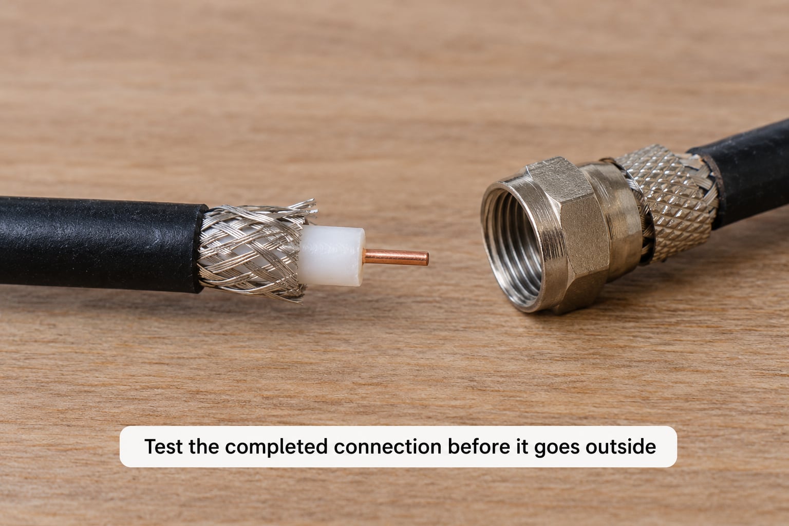
Match the connector to the coax, cut the cable square, then strip the jacket, shielding and dielectric in clean, even stages. The visual sign of a correct strip is a flat, even braid of consistent length with no loose strands poking out, and a clean white center conductor with no nicks.
- Confirm the pair. Match the connector part number against the cable type. RG6 and RG59 both often use an F connector, but the ferrule and grip ring dimensions differ, so an RG6 connector will not work on RG59 and vice versa.
- Square-cut the cable. Cut the coax with a sharp knife or side cutters, straight across, not at an angle. An angled cut leaves a wedge of jacket that stops the connector seating and is the second most common cause of a connector that will not go on.
- Strip the jacket. Set the stripper to your cable’s slot and rotate it two or three times. Take the first cut lightly. The jacket should come off in a ring and the braid underneath should stay intact and even.
- Trim the shield. Fold or comb the braid back and trim it to the length the connector instructions specify, usually a few millimetres. Do not leave a long fringe and do not cut so short that the shield cannot be clamped. Leave a short unshielded stub between the shield edge and the center conductor, ideally no more than a few millimetres, because that exposed length acts as an unshielded stub and raises VSWR.
- Strip the dielectric. Remove just enough foam to expose the center conductor to the connector’s contact depth. Do not nick the conductor while trimming the foam, and do not cut the center conductor shorter than the contact requires.
- Inspect before you attach anything. Look down the cable. If any braid strand reaches toward the center conductor, trim it back now. This is the moment to catch it, because once the connector is on you cannot see it.
That inspection step is the whole game. A connection that looks clean at this stage will test clean after assembly; one with a stray strand under the ferrule will not, and you will not be able to see the difference afterwards.
Attach a solderless connector: crimp, compression or twist-on
For a compression or crimp-on connector, the sequence is ferrule onto the jacket, shield contact, connector fully seated, then a firm squeeze with the matching tool, and finally strain relief. Follow the connector manufacturer on die compatibility, because crimp dies are not interchangeable between cable sizes.
- Slide the ferrule on first. For a crimp-on F and most PL-259 styles, the ferrule or grip ring goes onto the cable before the connector body. Push it down over the jacket until it stops.
- Seat the connector. Push the connector body over the cable so the shield enters the barrel and the center conductor reaches the contact. It should stop against the dielectric. If it will not seat and the jacket is bunching on the inner ferrule, strip a little more jacket off and push again.
- Crimp the ferrule. Put the grip ring into the correct die and squeeze firmly until the tool releases. For compression fittings, use the compression tool the same way, driving the ferrule into the connector body rather than into a loose ring.
- Check the ferrule seat. The ferrule should be flush with the shoulder of the connector, with no gap. A visible gap means the crimp did not engage and the joint will pull apart.
- Do the pull test. Pull the cable body, not the center conductor, with firm steady pressure. A good crimp will not move. Anything that twists or slides means redo it.
- Add strain relief. A strain-relief boot or a wrap of self-amalgamating tape takes the tug off the joint. Strain on the ferrule is what eventually pulls a good termination apart.
For a twist-on F connector the order is much shorter: strip, push the twisted ferrule over the cable, then twist the body on until the tapered sleeve compresses the braid into place. Tighten it until it is snug and the body no longer rotates freely. Do not overtighten, which crushes the braid and the foam.
Solder a PL-259 or other soldered connector
A soldered joint is a controlled heat process, not a blob of solder. The joint is sound when the solder has wetted both surfaces and flowed; a cold joint looks dull and beaded, a solder ball sits on top without wetting, and a burnt joint means you held the iron on the cable too long.
- Prepare the surfaces. Tin the center conductor and the connector’s solder lug before assembly. Tin the shield and the connector’s shell the same way, working heat into the lug rather than the cable.
- Flow a little flux. Flux is what makes solder wet metal instead of sitting on it. Use a no-clean electronics flux and keep it off the dielectric where possible.
- Distribute the heat. Heat the lug, not the cable. Hold the iron against the metal part and let the solder run into the joint. A coax jacket scorched or melted by the iron has lost its dielectric strength, and that is a joint you should cut off and start again.
- Let it cool still. Do not wiggle or blow on a fresh joint. Movement while it cools is what produces a dull, grainy, cold joint.
- Inspect. A properly wetted joint is smooth and slightly concave, with a fine silvery skin. A ball sitting proud of the lug has not wetted. Reheat it with more flux and let it flow again.
Wrap the exposed dielectric in electrical tape while you rework a joint, which stops a stray strand bridging the gap as you go.
Test the completed connection before it goes outside
A multimeter tells you in seconds whether the joint is good. Put one lead on the center pin and the other on the shell: a reading near zero ohms means a probable short to shield and the connection must be corrected before use. Then check the other way, from the center pin to the bare center conductor at the far end of the cable, and confirm the shield runs continuous.
Two tests, both quick. Center to shield should read open, usually an over-range indication or infinity. Center conductor to center conductor should read close to zero ohms on a healthy run, and the shell to shell should also read close to zero. A reading that drifts or sits somewhere in between points to a partial short, often moisture or a strand under the ferrule.
Then do the visual pass. Look for a ferrule flush with the shoulder, a braid folded neatly and captured, a center conductor seated in the contact, and no jacket crushed by the tool. After that comes weatherproofing, but not before the test. A joint sealed and then found to be shorted is a joint you have to cut off again.
For outdoor and marine runs, the community standard is self-amalgamating tape over the joint, then a bead of silicone sealant, then a heat-shrink boot over the top. Plain electrical tape alone is not a seal, and neither is a tight wrap of tape pretending to be strain relief.
Common Mistakes: Why Each One Fails and How to Fix It
Almost every bad coax termination traces back to one of a handful of errors, and each of them fails for a specific reason. Fixing the symptom without knowing the cause usually means doing the same job twice.
Wrong connector size for the cable. A connector for thinner coax will not seat properly and a connector for thicker coax will not crimp correctly. Match part numbers to the cable, and change the connector, not the technique.
Uneven or angled strip. A stepped or angled strip leaves thick sections of jacket that stop the connector going fully home, or a sliver of foam that folds the braid into the center conductor. Square the cut first and strip in two gentle passes rather than one heavy one.
Loose or splayed braid. Strands that fan outward and touch the center conductor produce a dead short and total signal loss. Fold the braid back tidily and trim it to length, and comb out anything pointing inward.
A stranded conductor caught under the ferrule. If the center conductor is not fully seated and a strand is trapped in the crimp, the contact is intermittent at best. It must be pushed fully in, with no strand in the ferrule path.
Over-crimping. Crushing the ferrule too hard deforms the connector body, flattens the barrel and can crack the dielectric. Firm and square is right; crushing is not.
Insufficient heat when soldering. A cold or solder-balled joint has high resistance and fails intermittently in rain or when the cable flexes. Reheat the lug with flux and let the solder flow and wet the metal.
Overheating the cable. Holding the iron on the cable jacket or braid melts the foam dielectric and scorches the jacket. The joint may look fine and fail later. Heat the connector, not the cable.
Poor or absent strain relief. Without it, wind and handling load the ferrule directly and the joint eventually pulls apart. Add a boot or a wrap of self-amalgamating tape before you seal the joint.
Testing only after weatherproofing. Once the joint is sealed, diagnosing it means cutting it off. Test with the multimeter first.
Symptom, likely cause and fix
Start from the symptom you are actually seeing, because no signal and intermittent no signal have very different causes. The table maps the most common reports to the cause behind them and the fix.
| Symptom | Likely cause | Fix |
|---|---|---|
| No signal at all, dead short on the meter | Braid touching the center conductor | Cut the connector off, re-strip, comb the braid back and trim it |
| Signal cuts out when the cable is moved | Stranded conductor under the ferrule, or a cold solder joint | Re-seat the conductor fully or reflow the joint with flux |
| Connector will not slide onto the coax | Too much jacket left, or the wrong connector size | Strip a little more jacket, or change to the matching connector |
| Ferrule sits with a visible gap to the connector | Wrong die size, or crimp did not engage | Recrimp with the die specified for that cable and connector |
| Works dry, fails in rain | Unsealed joint or water in the connector | Replace the joint and seal with self-amalgamating tape and sealant |
| Intermittent dropouts after installation | Foam dielectric damaged or nicked during stripping | Cut back to sound cable and terminate again |
| No signal on only one end of the run | Open center conductor or a failed connector at that end | Test continuity end to end and rebuild the suspect end |
Three closing tips. Choose the connector for the job rather than for what is in the drawer, use the ferrule and die combination the manufacturer names for your cable, and treat any outdoor joint as unfinished until it is sealed and you have tested it first. Nothing else in coax work matters quite as much as those three.
Frequently Asked Questions
Is it better to solder or use a solderless coax connector?
Both are perfectly acceptable and a correctly made crimp joint is as reliable as a soldered one, which is why solderless is the standard for TV, CCTV and field work. Solder is worth the extra effort where the joint must be permanent and repairable, such as a rooftop ham feedline, or where you are attaching directly to an antenna element. The deciding factor is not quality but access: if you can get the tools to the joint, crimp it, because crimp is faster and repeatable.
Why does my newly installed PL-259 connector show low resistance?
Because the center conductor is touching the shield, which is a dead short rather than a working connection. Common causes are braid strands left splayed across the center pin, a center conductor that was not pushed fully into the contact, or a length of braid trimmed too short so the shield and the conductor are exposed together. Cut the connector off, re-strip the cable, comb the braid back and trim it, then re-test before rebuilding.
Do RG-58 and RG-8X use the same BNC connector?
No, and this catches people out regularly. RG-58 uses a 50 ohm BNC fitted with the standard ferrule, while RG-8X is a larger 50 ohm cable that needs a ferrule sized for its thicker jacket and braid. Many manufacturers sell both versions under the same BNC name. A BNC made for RG-58 will not crimp correctly on RG-8X, so check the cable diameter and the ferrule marking before you start.
How can I test a coax connector before installing it on an antenna?
Use a multimeter on the finished end. Center pin to shell should read open, not zero, and a near-zero reading means a probable short to shield. Then check the center pin to the bare conductor at the far end for near-zero ohms, and the shell to the far end the same way, to confirm the cable itself is continuous. Add a gentle pull test on the ferrule. It takes under a minute and catches almost every failure before the run goes up.
Can I learn how to install coax connectors without soldering mistakes on outdoor feedlines?
Yes, and outdoor feedlines are exactly where careful work pays off, because a joint under a roof or on a mast is expensive to revisit. The two habits that prevent mistakes are the same indoors: check the stripped end visually for any braid strand reaching the center conductor, and meter-test the joint before you seal it. Seal outdoor terminations with self-amalgamating tape, silicone sealant and a heat-shrink boot, never electrical tape alone.
Conclusion: Start With a Short Offcut and a Meter
The safest path through how to install coax connectors without soldering mistakes is short and unglamorous. Identify the cable and the matching connector before you start, strip to the dimensions that connector specifies, keep the exposed stub between shield and center conductor as short as you can, and secure real mechanical strain relief on the ferrule.
Then meter-test the joint before it goes into service, and before you seal anything. Center to shield reads open, end to end reads near zero, and a firm pull confirms the crimp.
Practise the whole sequence on a 300 mm offcut first. When the strip looks even, the ferrule sits flush and the meter passes, the same three things will happen on the run that counts.