Learning how to measure RF exposure for your station comes down to two jobs, and hams usually need both. The first is the paper evaluation the FCC asks for: gather your power, frequency, antenna gain, duty cycle and nearest-person distance, then run them through a free calculator to get a compliance distance. The second is physical measurement with a field strength meter, which tells you what your station is actually radiating at the places people stand.
The calculation takes about twenty minutes for a simple station. The measuring takes an afternoon, mostly spent moving a probe around with a coax extension cord and writing down numbers. Doing the calculation first is worth it, because it tells you where to point the meter and roughly how big the readings should be.
One thing to get straight early: since May 3, 2021, every amateur station must be evaluated, and the old power-level exemption table that let many small stations skip it is gone. The grace period ended May 3, 2023. As of 2026 nothing gets filed with the FCC and there is no form or fee, but the duty to evaluate your station is on you.
Table of Contents
- 1What You Need
- 2Step-by-Step
- 3Step 1: Document the Station and Identify Exposure Points
- 4Step 2: Calibrate and Check the RF Meter
- 5Step 3: Measure Around the Antenna and Feed Line
- 6Step 4: Measure the Operating Position
- 7Step 5: Compare Results With Conservative Limits
- 8Step 6: Recheck After Changes
- 9Common Mistakes
- 10Frequently Asked Questions
- 11What is a safe level of RF radiation?
- 12How do you measure radio frequency radiation at a ham station?
- 13Can a field strength meter prove I am compliant with RF exposure limits?
- 14Does RF exposure apply to handheld and mobile radios?
- 15What is the difference between controlled and uncontrolled RF limits?
- 16When should I get a professional RF safety evaluation?
- 17Conclusion
What You Need
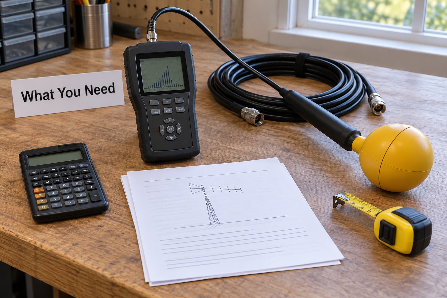
Start with the paperwork side, because the meter is useless if you do not know what your station is transmitting.
- Station details: every antenna type and its dimensions, mounting height above ground, where the feed point sits, and which bands each one covers.
- Transmitter details: output power in watts for each radio, plus a realistic duty cycle for the modes you actually use.
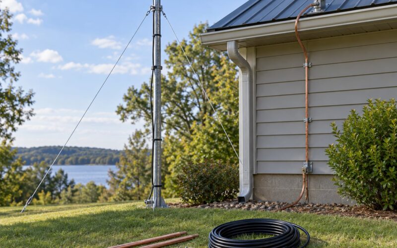
- Feed line routing: where the coax runs, how long it is, and whether any of it is close to people or enters living space.
- Distance data: how far the closest person can get to the antenna or feed point, measured with a tape rather than guessed.
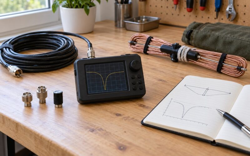
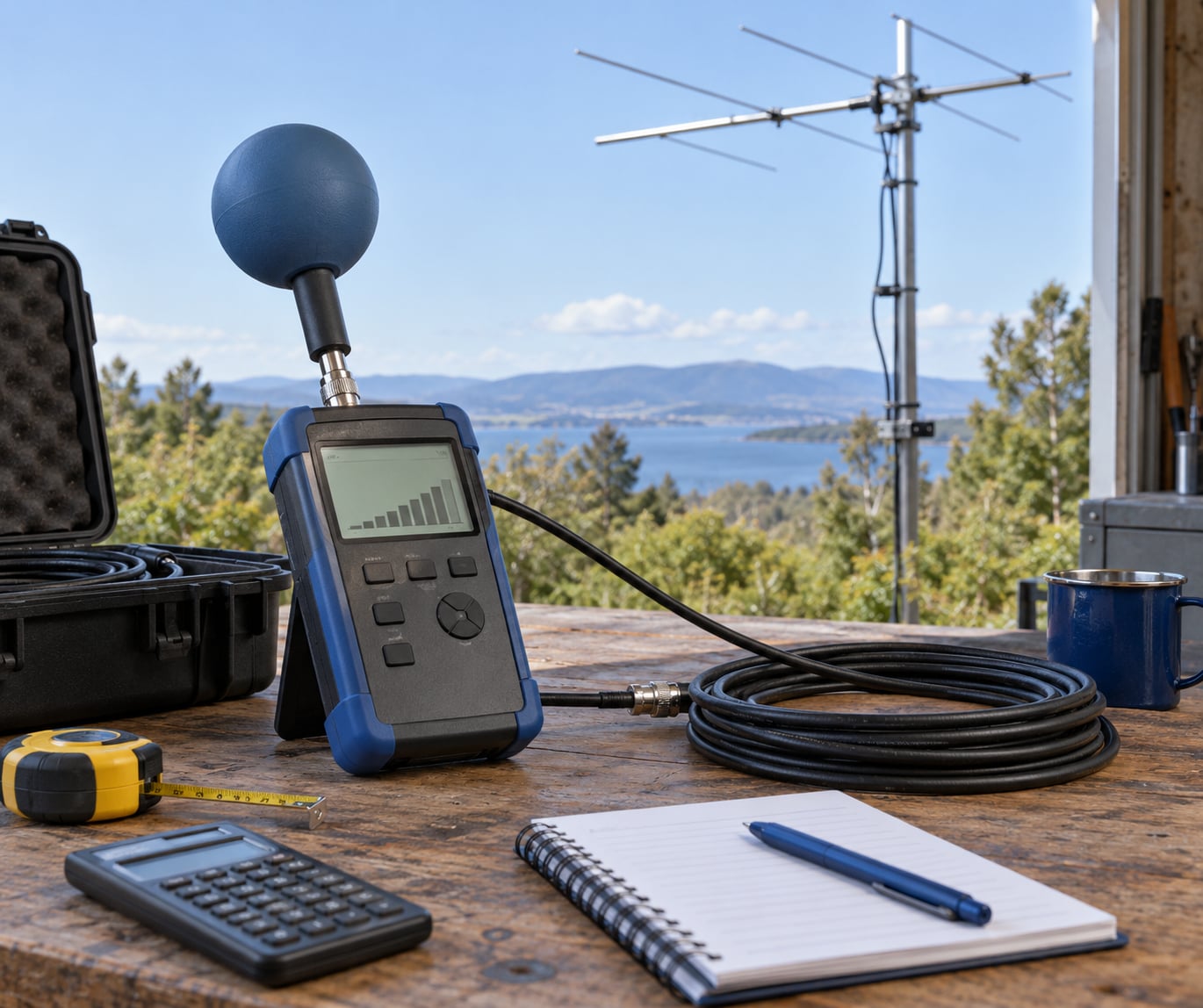
- A field strength meter: a calibrated meter with an isotropic or near-field probe covering the bands you transmit on.
- Coax extension: enough length (a common length is 25 to 50 feet) that the meter stays at arm’s length while you hold the probe.
- A notebook or spreadsheet: every reading needs its position, height, frequency, power and mode written down next to it.
Two tools do most of the paperwork for you. The ARRL RF Exposure calculator, built on the method in OET Bulletin 65 Supplement B, is the reference tool that most clubs point new licensees to. Exposure Forge is a newer web tool with a friendlier layout that produces the same compliance distance for most stations. Run your station through both if you can, since agreement between them is a cheap sanity check.
ARRL also publishes RF Exposure and You by Ed Hare, W1RFI, as a free download. It is the reference most clubs hand out at license classes, and it walks through the whole regulatory background.
On the meter side, you have two categories to choose from. A calibrated field strength meter measures V/m or mW/cm2 and is the tool for pointing at a transmitter and reading the actual field. A personal RF monitor, worn on the belt or clipped to a lanyard, is a relative indicator with the transmitter near you, useful for confirming that a hotspot has gone away but not useful for compliance work. Buy or borrow the first kind if you want numbers you can record and show a neighbor or a zoning board.
If you have never used an RF meter before, note that cheap HF-field indicators built for receiver troubleshooting are not the same instrument. They are typically uncalibrated and band-specific. They can tell you relative hot and cold spots. They cannot give you a defensible number.
Step-by-Step
Step 1: Document the Station and Identify Exposure Points
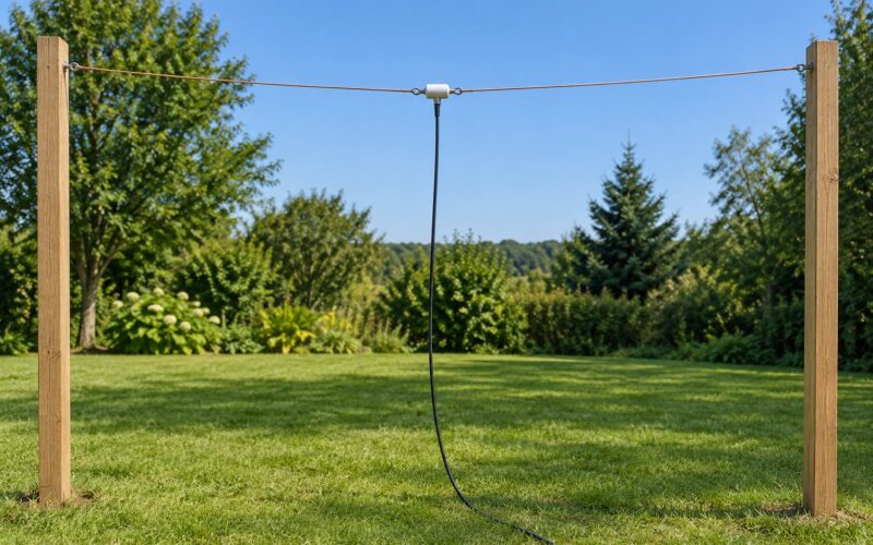
Write the station down before you touch any equipment. Record each antenna’s type and physical dimensions, its height above ground, the feed-point location, and the bands it covers.
For each transmitter, note the output power in watts, the modes you run, and a duty cycle you can defend. Common starting assumptions for a station that is not dedicated contesting:
| Mode | Typical duty cycle used for RF exposure work | Note |
|---|---|---|
| SSB voice | 20 percent | Transmit only, not the receive window |
| CW | 40 percent | Long ragchew-heavy operating pushes this up |
| FM | 100 percent | Continuous carrier, no relief valve |
| FT8, JT65, FT4 and other digital | 100 percent | Almost always transmitting |
| Packet and APRS | 100 percent during bursts | Evaluate as continuous if transmissions are back to back |
The duty cycle matters because exposure limits are averaged over time. A 100-watt FM carrier running an hour is a different exposure case than 100 watts of SSB, even though the peak numbers look identical. That said, using the 100 percent figure is the conservative choice, and using it costs you almost nothing once you see how the distances come out.
Next, mark the places where people actually are. The feed point of a dipole in the attic is the highest-field spot on most home stations, and it is often only a few feet from a bedroom wall. Other usual suspects: coax runs through a wall or ceiling, a coax connector on the floor of the shack, a mobile whip on a parked car, and a handheld pressed against an operator’s head.
Measure the distance from the feed point to the nearest place a person can occupy, and measure it twice. The second tape measurement is always longer than the first.
Note the band plan too. The tighter limits sit in the VHF range, roughly 30 to 300 MHz, where the whole-body absorption is highest. A 6-meter beam at 100 watts can produce a longer compliance distance than a much bigger HF dipole at the same power, which surprises people every time.
Step 2: Calibrate and Check the RF Meter
Check the battery first, then the probe. Most meters refuse to give a sensible reading with a weak battery, and a dead meter that reads zero is worse than no meter because it looks like good news.
Verify the probe and instrument are matched. A probe designed for one frequency band will not read correctly on another, and mixing a high-frequency probe with a cable that is too long will roll off the top of your range exactly where you need it.
Confirm the units before you start. A meter set to read E-field in V/m and a meter set to read power density in mW/cm2 are measuring related things, and mixing readings from two meters on different scales is the single most common way people get a false picture of their station.
Run a quick functional check: hold the probe a foot or two away from a low-power handheld or a running transmitter at low power and confirm the reading moves in the direction physics says it should. If the needle sits at zero no matter what you do, you have a dead battery, an unpowered meter, or a probe that is not for your band.
Read the instrument manual for its calibration procedure. If the manual calls for a calibration source or a reference field at a specific distance, do that before you trust any number you write down.
Step 3: Measure Around the Antenna and Feed Line
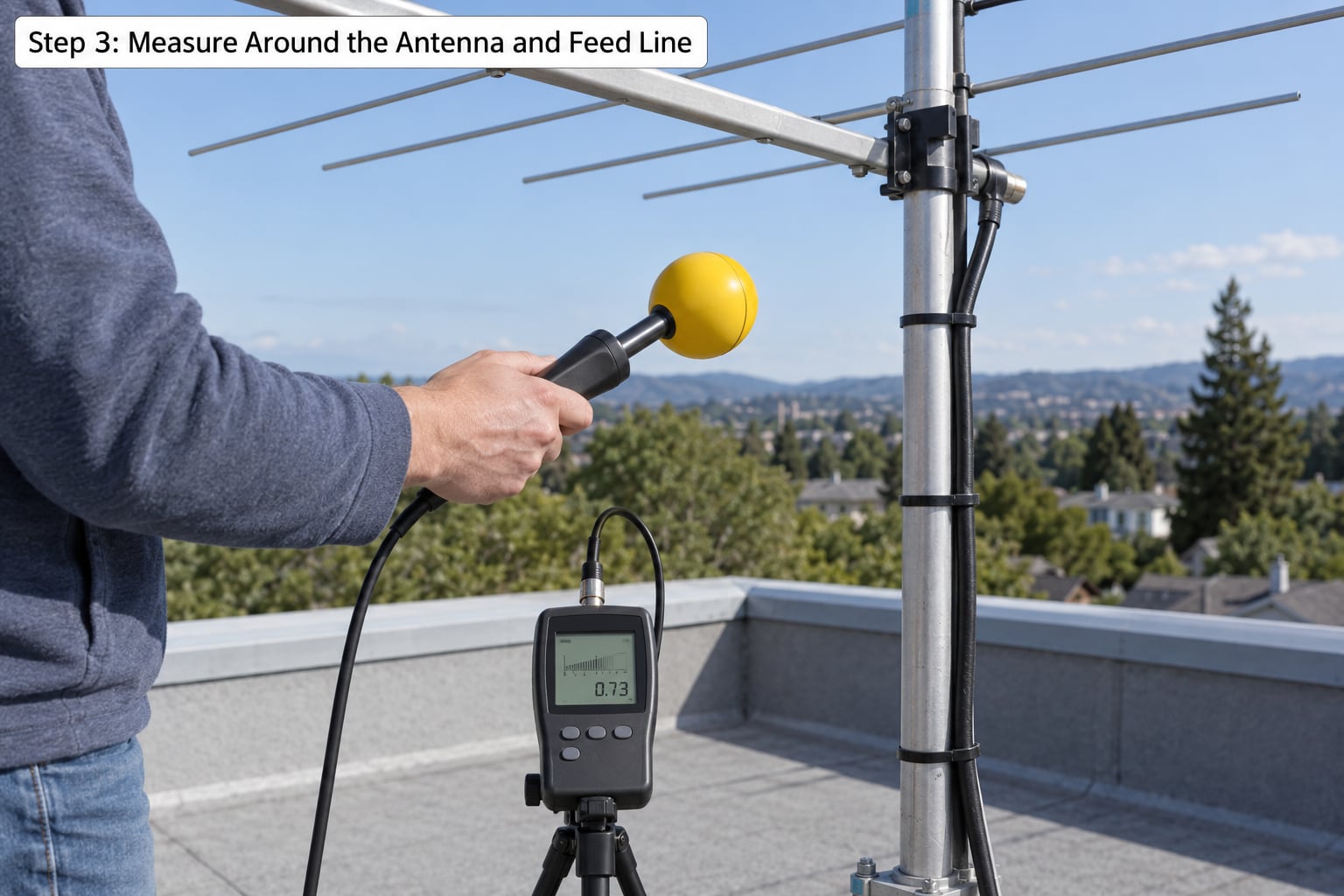
Start at the antenna, not at the radio. The strongest field on most stations is within a wavelength or two of the feed point, and that region is often missed entirely by people who measure only at the operating desk.
Hold the probe at waist height, roughly where a standing adult’s midsection sits, and move it in small steps around the feed point and along each element. Take a reading every foot or two, and write down the position for each one. A single spot measurement tells you almost nothing; a grid of readings tells you where the hotspot is.
Pay attention to orientation. A dipole radiates differently along its length than perpendicular to it, and the ends of the elements often show a higher reading than the center. Turning the probe on its side can also change a reading substantially, which is a good reminder that an electric-field probe alone is measuring one component of a complex field.
Measure twice under different conditions. First, transmit normally. Then transmit at your highest power with your highest duty-cycle mode, because that is the condition you have to stay inside. If you run a linear amplifier, the second pass is the one that matters.
Do the same walk along the coax. Run the cable the way it really runs, and stop at every point where it comes close to a person, passes through a wall, or terminates in a connector. Connector faults and poorly seated coax jumpers produce local heating and local fields that no end-of-feedline calculation will ever show you.
Expect reflections to distort the picture. A metal roof, a chimney, a neighbouring fence or the side of the house will reflect energy and create a secondary field region you did not plan for. If your readings do not fall off smoothly with distance, that is usually what is happening, and the calculator will not model it.
Step 4: Measure the Operating Position
Now sit at the radio and transmit. Measure at the position of your head, your hands and your torso while seated normally, and then repeat while standing, because those two positions give different numbers.
Walk the adjoining rooms. Close every door you normally close, then measure behind it. Do not assume a wall solves the problem; at some frequencies a wall with a window, a mirror or a stud cavity can be less effective than you expect, and the meter tells you what the wall actually does.
Measure the areas people outside your household can reach: the yard, the driveway, a shared walkway, a balcony. Those are uncontrolled locations and the limits applied there are the stricter of the two sets you must work to.
Keep the instrument reading and the RF field measurement in separate mental boxes. A field strength meter tells you the strength of the field at a point. Turning that into an exposure assessment for a person over time requires modelling, duty-cycle assumptions and judgment about what an exposure means, which is exactly the part the FCC asks you to document with a calculation rather than a meter.
That is not a reason to skip the meter. It is a reason to hold both tools. The calculation is the compliance document; the measurement is your evidence that the calculation matches your real station.
Step 5: Compare Results With Conservative Limits
Compare your readings to the MPE, or Maximum Permissible Exposure, for the frequency involved. Those limits come out of IEEE C95.1 and are implemented for broadcast and amateur stations through OET Bulletin 65, with Supplement B covering amateur stations specifically. The limits vary by frequency, and they are expressed differently depending on which standard you are working from.
Two sets of limits apply to a home station, and this is where most mistakes happen:
| Location | Who is there | Which limits apply | What it means for you |
|---|---|---|---|
| Controlled environment | Yourself and your household, who understand the exposure and can move away | More permissive controlled-area limits | Governs your shack, your attic feed point, your operating position |
| Uncontrolled environment | Neighbours, visitors, anyone without RF awareness | Stricter general public limits | Governs your yard, your roof access, shared space and anything near the property line |
If a single spot on your property could serve either group, use the stricter uncontrolled limit. A conservative reading costs you a slightly larger safe distance, and a larger safe distance is easy to arrange.
Do the arithmetic in the inverse square sense, because it dominates everything else. Field strength from an antenna falls off roughly with the square of distance, so halving the distance gets you four times the field strength. Moving the feed point of an attic dipole into the loft void instead of leaving it six inches under the ceiling planking is worth far more than dropping from 100 watts to 50.
That said, meter readings close to an antenna, inside the reactive near field, do not follow inverse square. They can be higher than the calculator predicts, sometimes dramatically so on a small antenna with high feed-point voltage. This is precisely why the physical check is worth doing, and why the conservative approach is to treat close-in measured hotspots as real until proven otherwise.
Now, compare your measured distance against your calculated compliance distance. If the distance where you measure down to the limit is larger than any place a person can actually stand, you are in good shape. If it is smaller, you have options: move the feed point, raise the antenna, drop power, cut the duty cycle, add a low-pass filter on the transmitter output if your band plan needs one, or simply mark off that area in your shack.
If your situation is complicated enough that a single feed point and a single power figure will not settle it, get a qualified RF safety assessment. A professional evaluation is warranted when several transmitters share a tower, when your antenna sits close to a property line or a public walkway, when someone has formally complained, when your local authority requires a certified evaluation for zoning or a building permit, or when a calculator result lands uncomfortably close to a boundary and you need an answer you can put in writing.
Step 6: Recheck After Changes
An evaluation is a snapshot of one station configuration. Repeat it when you change an antenna or its dimensions, change mounting height or feed-point location, increase output power, add a band or a new transmitter, reroute the coax, change your duty cycle habits substantially, or when a nearby structure changes the reflection pattern around your antenna.
A tower that grows a second antenna, a neighbour who erects a large metal roof or shipping container, or a new repeater group installation down the road can all change the field around your station without you touching anything.
Keep the record. A single page with your antenna dimensions, the calculator inputs, the compliance distances for controlled and uncontrolled areas, the date, and a few meter readings is enough. People have printed calculator results and used them as evidence in neighbour conversations and zoning discussions, and having dated documentation in hand is far stronger than repeating from memory.
If your operating life includes portable work, do the same thinking in the field. A handheld held against the head puts the radiator within centimetres of the skull, and the low power does not make that geometry friendly. Assessments of handheld use generally point at keeping the antenna away from the head and using an external microphone and speaker, not at the wattage. For mobile operation with a 25 to 50 watt radio and a 6 dBi whip, the compliance distance can land in the 10 to 15 foot range around the vehicle, which is why antenna placement and where the vehicle is parked both matter.
Attic and indoor antennas deserve their own note because they are the most common source of anxiety in club surveys. The feed point and the first stretch of each leg are the strongest field regions, and bedrooms sit exactly where those regions are. Moving the feed point up into the roof void, choosing a lower-loss feed line, or running the legs away from occupied rooms usually resolves it. Measure before you move anything, then measure again after, because the fix is cheap when you know where the problem was.
Common Mistakes
Measuring only at the radio. The field at your operating position is often the smallest number on your list. The feed point, the coax and the antenna ends are where the readings live. Walk the whole station.
Holding the probe wrong. A probe held against your body, or one you wrapped around your fingers, is measuring something meaningless. Keep the sensing element clear of metal and keep yourself at arm’s length from the probe on the extension cable.
Comparing readings from two different meters in two different units. One meter reading V/m and another reading mW/cm2 does not give you two comparable numbers. Standardise before you compare, or use each meter for its own purpose and do not draw conclusions across instruments.
Ignoring reflections. Smooth readings are not the goal. A building, a roof, a fence or a tower nearby creates secondary field regions, and those regions can exceed the primary one at surprisingly short distances.
Transmitting at a power you never run. Testing at full power is conservative and useful. Testing at an unrealistic high power across a band you do not operate just produces numbers that scare you without informing you. Measure the condition you actually transmit in.
Treating one reading as proof. A single comfortable number at one spot proves only that one spot, at that moment, with that antenna orientation, in that band. Exposure is about the worst case over time and over the places people stand.
Confusing the meter with the assessment. A personal RF monitor tells you a transmitter is nearby. A compliance evaluation is a calculation against MPE limits, documented with your inputs and dates. Use both, and know which one you are quoting.
Forgetting the second transmitter. On a multi-antenna tower, exposure from separate sources can add. Evaluate each antenna on its own, then consider whether the worst-case field regions overlap. When they do and the combined case is close to a limit, that is a case for a professional evaluation rather than more arithmetic at the kitchen table.
Frequently Asked Questions
What is a safe level of RF radiation?
Safe levels are set as Maximum Permissible Exposure limits derived from IEEE C95.1 and applied by the FCC through OET Bulletin 65, including Supplement B for amateur stations. Limits vary with frequency, and controlled areas, where you and your household can move away, have more permissive limits than uncontrolled areas near neighbours and the public. The practical rule is to measure your field, compare it to the limit for your band, and keep people outside the compliance distance your calculator returns.
How do you measure radio frequency radiation at a ham station?
Use a calibrated field strength meter with a probe matched to the band you are testing on. Hold the probe at waist height, step around the feed point, the elements and the coax run, and record a reading every foot or two with the position noted. Repeat at your highest power and longest duty cycle. Compare the highest readings with the compliance distance from an ARRL or Exposure Forge calculation, and treat close-in measured hotspots as real.
Can a field strength meter prove I am compliant with RF exposure limits?
Not on its own. A meter measures field strength at a point, in V/m or mW/cm2, and it is invaluable for finding hotspots and confirming that a fix worked. Compliance rests on a documented evaluation using transmitter power, frequency, antenna gain, duty cycle and the nearest person distance. The FCC expects that calculation. Use the meter to support it, not to replace it.
Does RF exposure apply to handheld and mobile radios?
Yes. Every transmitting station falls under the same requirement to evaluate exposure, and a handheld has an awkward geometry because the antenna sits centimetres from the operator’s head. Keeping the handheld’s antenna away from the head with a speaker microphone is the usual mitigation. A 25 to 50 watt mobile with a 6 dBi whip can put the compliance distance in the 10 to 15 foot range around the vehicle, so where you park matters too.
What is the difference between controlled and uncontrolled RF limits?
Controlled areas are places where people know about the exposure and can move away, such as your own shack, attic or household. Uncontrolled areas are anywhere a neighbour, visitor or passer-by can be standing. The FCC applies more permissive limits in controlled areas and stricter general public limits in uncontrolled ones. Wherever a spot could serve either group, use the stricter uncontrolled limit and treat the result as your target.
When should I get a professional RF safety evaluation?
Get qualified help when several transmitters share one tower, when an antenna sits near a property line or public walkway, when a neighbour has formally complained, when a local authority wants a certified evaluation for zoning or a permit, or when your own calculation lands close to a limit you cannot comfortably clear. Professionals can model near-field behaviour, combined sources and structural reflections that a handheld meter and a spreadsheet will not.
Conclusion
Write down your station today: antenna dimensions, mounting height, feed-point position, power, bands and duty cycles. Run those numbers through the ARRL calculator or Exposure Forge, get your controlled and uncontrolled compliance distances, and then spend an afternoon with a field strength meter walking the feed point, the elements, the coax run and your operating position. Record every reading with its conditions, and use conservative engineering judgment or a qualified RF safety evaluation before operating where the fields are unusually high.