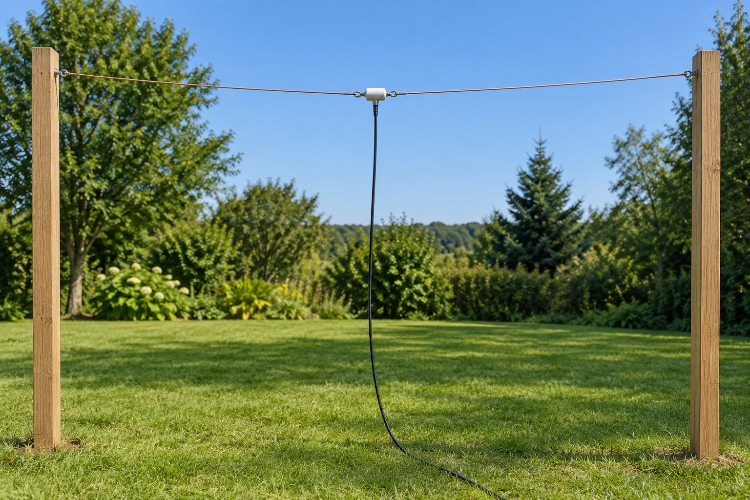
A simple HF wire dipole antenna is one continuous length of insulated copper wire cut to roughly a half wavelength and fed at its centre with 50-ohm coaxial cable. Total length in feet equals 468 divided by the frequency in megahertz. Cut it, hang it clear of metal, and it will work on the band it was designed for without a tuner.
It is the first antenna I would build for any HF band, and probably the last one I would ever replace. Two lengths of wire, a couple of insulators, some rope and an afternoon. Everything else on the HF menu costs more and does less for a beginner.
Here is how to make a simple wire dipole antenna for HF the way I would: calculate the length first, cut it slightly long, hang it in the clear, then trim. That order matters, because wire that is too short is the one mistake you cannot undo easily.
Table of Contents
- 1What You Need
- 2How to Calculate Your Wire Dipole Length
- 3Step-by-Step
- 41. Pick the band and calculate the length
- 52. Cut the wire and fit the end insulators
- 63. Build the centre connection
- 74. Add spreaders if you need an inverted V
- 85. Mount the antenna in the open
- 96. Route the coax at right angles
- 107. Seal and secure
- 118. Connect to the radio and check SWR
- 12How to Feed and Tune the Dipole
- 13How to Install the Antenna Safely
- 14Common Mistakes
- 15Frequently Asked Questions
- 16How long should my dipole antenna be?
- 17Which HF bands are best for a beginner dipole?
- 18Do I need a tuner to use a dipole antenna?
- 19How high should I hang a dipole antenna?
- 20How close can a dipole be to a roof?
- 21Can one dipole receive shortwave broadcasts as well as ham signals?
- 22Conclusion
What You Need
Keep the parts list short. You can build this whole antenna with items from a hardware store and one electronics supplier.
- Wire. 50 to 100 feet of 14 or 16 AWG stranded copper, or hard-drawn copper wire. Stranded is easier to handle; hard-drawn stretches less as you tension it. Buy more than the calculated length so trimming is possible.
- Two end insulators. Egg insulators or dogbone insulators. These hold the wire ends away from whatever you tie to, and keep the high-voltage ends off metal.
- A centre connection. Either a centre insulator designed for dipole feed, or a SO-239 connector, a BNC connector, or two binding posts on a non-conductive plate. This is where the feeder attaches.
- 50-ohm coaxial cable. RG8X or RG213 for a permanent rooftop install, RG58 for lighter duty. Length it generously so you can reach the radio and still leave a drip loop.
- Support hardware. Halyard rope, mast or pipe for the high point, and guylines if the antenna is tall or exposed.
- Optional: a 1:1 current balun, PVC spreaders for inverted V layouts, heat-shrink tubing, ring terminals, and a socket for weatherproofing the coax where it meets the antenna.
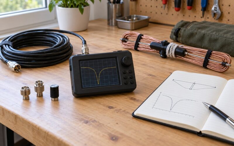
Tools are ordinary: a tape measure, wire cutters, a multimeter, and either an SWR meter or an antenna analyzer. Soldering gear is helpful but not required. Binding posts and crimped ring terminals give a perfectly good connection without a soldering iron, which is why several no-solder builds online work so well.
How to Calculate Your Wire Dipole Length
The formula is simple: total length in feet = 468 divided by frequency in MHz. The metric version is total length in metres = 143 divided by frequency in MHz. That single number is the total of both legs, not the length of one leg.
Why 468 and not the free-space 492? A half wavelength in air would give 492, but real wire has diameter, it is usually insulated, and the ends are held by an insulator and a support rather than ending in free space. Those details let the wire hold more charge at the ends than pure theory predicts, so the antenna needs to be physically shorter than the free-space figure. The 468 constant folds that end effect in. For a thick or heavily insulated wire you may need even less, which is why the 143 metre constant is the sensible one to start from.
Here is a cut-length chart for the common amateur bands, worked out in the middle of each band.
| Band | Frequency (MHz) | Total length (ft / m) | Each leg (ft / m) |
|---|---|---|---|
| 160 m | 1.9 | 246 ft / 75 m | 123 ft / 37.5 m |
| 80 m | 3.7 | 126 ft / 38.5 m | 63 ft / 19.3 m |
| 60 m | 5.4 | 86.7 ft / 26.4 m | 43.3 ft / 13.2 m |
| 40 m | 7.15 | 65.5 ft / 20.0 m | 32.7 ft / 10.0 m |
| 30 m | 10.15 | 46.1 ft / 14.1 m | 23.1 ft / 7.0 m |
| 20 m | 14.2 | 33.0 ft / 10.1 m | 16.5 ft / 5.0 m |
| 17 m | 18.1 | 25.9 ft / 7.9 m | 12.9 ft / 3.9 m |
| 15 m | 21.2 | 22.1 ft / 6.7 m | 11.0 ft / 3.4 m |
| 12 m | 24.9 | 18.8 ft / 5.7 m | 9.4 ft / 2.9 m |
| 10 m | 28.4 | 16.5 ft / 5.0 m | 8.2 ft / 2.5 m |
Worked example for a 20 metre dipole: 468 divided by 14.2 gives about 33 feet total, so each leg is about 16 feet 6 inches. At 10 metres, 468 divided by 28.4 gives 16 feet 5 inches total, or roughly 8 feet 3 inches per leg.
Two allowances matter in practice. First, cut 6 to 12 inches longer than the chart says and trim after it is up; taking wire off is easy, adding it back means redoing a joint. Second, nearby objects change the result. A roof, a rain gutter, a metal fence or a chimney will pull the resonance off the calculated frequency, usually downward, so the installed antenna often ends up shorter than the chart in the real world.
Step-by-Step
1. Pick the band and calculate the length
Choose one band to start. Calculate the total length with the formula, then add 6 to 12 inches of trimming allowance before you cut.
You will know you have done this right when both legs plus the centre connection come out symmetric.
2. Cut the wire and fit the end insulators
Cut one continuous piece for the whole element if you can, or two equal legs if you are using a centre connector. Attach an egg or dogbone insulator at each end, then secure the wire inside it with a crimped terminal, a knot through the insulator hole, or a wrap-and-solder joint.
Test for continuity from the wire end to the insulator fitting. A beep means the path is solid; no beep means a bad joint that will corrode within a season.
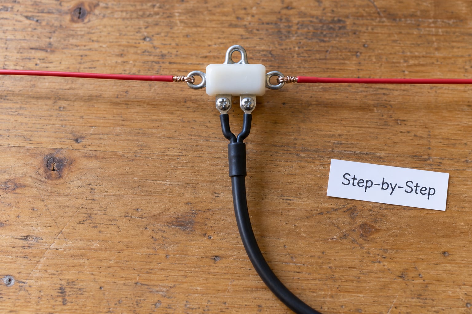
3. Build the centre connection
Join the two legs at the centre using a centre insulator, or bolt both legs onto the two terminals of a coax connector mounted on a plastic plate. Keep the two legs as close to equal as you can and keep the metal hardware as small as practical.
A good centre joint measures close to zero resistance across the two legs with your meter, and the coax shield is the only other connection to it.
4. Add spreaders if you need an inverted V
If only one tall support is available, cut two PVC spreaders a little shorter than the distance between the centre and each insulator, and fit them so the legs stand off the mast. Without spreaders the legs hang together and the pattern changes.
Spreader length is not critical. Straight, separated legs are what matters.
5. Mount the antenna in the open
Hang it as high and as far from metal as you can. For a flattop you need two supports; for an inverted V one high point is enough. Aim for the lowest point of the antenna to sit above the reach of anyone on the ground.
Height shows up in your signal reports. A dipole at 40 feet usually beats the same dipole at 20 feet, sometimes by a lot, because more of the low-angle radiation that carries long distances clears the ground.
6. Route the coax at right angles
Run the feeder away from the antenna at 90 degrees to the elements, or drop it straight down from the centre. Leave a drip loop below the entry point so water runs off instead of into the connector, and strain-relieve the cable so the weight of the coax never pulls on the joint.
If your SWR reading shifts when you reorient the coax, the feeder is coupling into the antenna. Move it and check again.
7. Seal and secure
Weatherproof the connector with self-amalgamating tape, heat-shrink and a socket, and check that the antenna and its ropes are firmly anchored. Insulate the halyard from the wire; a rope that touches a live element under power will cook.
A tug on the wire and the insulator should produce no movement and no crackling.
8. Connect to the radio and check SWR
Run the coax to your transceiver with the transmitter at low power, and measure standing wave ratio across the band. Note where the SWR dip falls and how wide it is.
An SWR dip below 1.5:1 across the part of the band you care about means you are in good shape. Anything under 2:1 is workable with almost any solid-state radio. See the tuning section for what to do next.
How to Feed and Tune the Dipole
A dipole is a balanced antenna: the two legs carry equal and opposite currents. Coaxial cable is unbalanced, with the braid acting as a return path. That mismatch is what a balun addresses, and it is why some dipoles suffer common-mode current flowing down the outside of the coax, showing up as interference in neighbouring TVs, FM receivers and shortwave sets.
A 1:1 current balun blocks that common-mode current without changing the impedance. It is the right choice for a plain dipole fed with coax, and it is cheap. A 4:1 balun transforms the roughly 72 ohm feed impedance down toward 50 ohm, which mainly helps folded dipoles or when you are deliberately feeding a mismatched setup through a tuner. Skip the balun if the antenna is a simple centre-fed dipole with coax running straight down and your neighbours are happy.
Feeding one end of the wire instead of the centre gives you an end-fed antenna. It needs a counterpoise, is far more sensitive to what is around it, and produces more unwanted harmonics. For a first build, the centre-fed dipole is the calmer choice.
For tuning, read forward and reflected power on an SWR meter or use an antenna analyzer. If the dip sits below the band you want, make the antenna longer. If it sits above, make it shorter. That is the whole rule.
A tuner is a matching network, not a fix. It lets your radio run at a comfortable load while the antenna works off resonance, at some efficiency cost. Experienced operators will tell you the antenna does not have to be resonant, only usable, and they are right. It is still better to start with a resonant single-band dipole and add a tuner only if you need to work other bands.
Odd harmonics are the cheap multiband trick. A 40 metre dipole also resonates on 20 m, 15 m and 10 m, because those are even multiples of its half wavelength. Current, and therefore efficiency, drops with each harmonic, so the higher bands are usable but not flat. A fan dipole with several lengths of wire stacked in parallel gets closer to full performance on three or four bands without a tuner.
How to Install the Antenna Safely
An antenna carries high RF voltage at its ends, sometimes enough to give you a shock you will remember. Keep both insulated ends out of reach of anyone who could touch them, and keep the lowest point of the antenna well above head height.
Choose a support that will still be there in a storm: a proper mast, a treated pole or a strong tree limb. If the antenna is tall or exposed, add guylines. Never work near overhead power lines, and never raise a mast where it could contact them. If your property has lines crossing it, leave the climbing and rigging to a qualified antenna installer.
Follow local electrical and property rules. Homeowner associations and municipal ordinances can restrict antenna height and placement, and it is much easier to check before you climb than after a neighbour complains.
Weatherproof every joint, and disconnect or lower the antenna before a severe storm or lightning event. Do not put it up on a day when you would not want to be holding a wet rope in the wind.
Common Mistakes
Cutting the wire too short. The most repeated complaint from first-time builders, and the most annoying one. You cannot easily add wire back to a centre connection. Cut long, measure twice.
Measuring only one leg. The 468 figure is the total of both halves. Halving after cutting is right; cutting the total length and then halving the piece is how people end up with a very short antenna.
A weak centre connection. A twist that loosens, a solder joint that beads and cracks, or a connector with no strain relief will fail in the weather. Use a proper connector or binding posts, crimp terminals, and a tie-off that takes the cable weight.
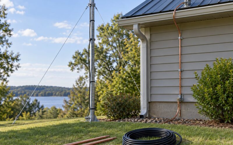
Mounting close to metal. Roofs, gutters, fences and masts detune the antenna and skew the pattern. More often than not, this is the real reason a brand new dipole shows SWR that makes no sense. Move the antenna before you blame the wire.
Running the coax alongside the antenna. Parallel coax and elements interact. Route the feeder at 90 degrees or let it drop away from the centre, and add a drip loop.
Expecting a random cut to be perfect. The formula is an excellent starting point, not a measurement. Trim with an SWR meter or analyzer, checking the part of the band you actually intend to use.
Next steps once it is working: measure your SWR at a few powers, compare a low band with the band above it, and if you want more, look at a fan dipole or a folded dipole with a 4:1 balun rather than a pile of separate antennas.
Frequently Asked Questions
How long should my dipole antenna be?
Total length in feet is 468 divided by the frequency in megahertz, and that figure covers both legs together. A 20 metre dipole at 14.2 MHz comes to about 33 feet total, so roughly 16 feet 6 inches per side. In metres, divide 143 by the frequency in MHz. Cut 6 to 12 inches longer than the calculated figure so you can trim after the antenna is installed and its surroundings are affecting it.
Which HF bands are best for a beginner dipole?
The 40 metre and 20 metre bands are the easiest starting points. Both are wide enough to cover with a single cut wire, neither needs an enormous yard, and both carry plenty of activity. A 20 metre dipole is about 33 feet total and fits in most backyards. The 10 metre band is only 16 feet long and works on its odd harmonics, but it is empty without sunspot activity, so it makes a poor first choice for daily operating.
Do I need a tuner to use a dipole antenna?
No, not if you cut it for the band you want to work. A correctly sized single-band dipole is close to 72 ohms at resonance and needs no tuner at all. A tuner becomes useful when you want multiband operation on one wire, when the antenna is badly compromised by height or nearby objects, or when you are using an end-fed wire. A tuner matches the load to the radio; it does not make a mismatched antenna radiate better.
How high should I hang a dipole antenna?
As high as you can get it and as far from metal as possible. Height is the single biggest factor in real performance, because it lets more low-angle radiation travel long distances without skimming the ground. A 40 metre dipole at 40 feet will usually beat the same antenna at 20 feet by several S-units on long paths. In a typical residential yard, 20 to 30 feet is realistic and still perfectly usable.
How close can a dipole be to a roof?
Some clearance helps, but a modest gap works. The antenna detunes when metal is electrically close to its elements, so aim for at least a foot or two of separation from metal roof edges, gutters and chimneys wherever you can. If the antenna must hang low over the roof, expect the SWR dip to shift downward and plan to trim for the real installed position rather than trusting the calculated length.
Can one dipole receive shortwave broadcasts as well as ham signals?
Yes. A half-wave dipole is not a ham-band antenna; it is a resonant receiving antenna for whichever band you cut it for. Build one for the 49 metre shortwave broadcast band near 6 MHz, and you will get good results on those stations. Shortwave listeners often run several of these cheap wire antennas, one per band, because each is a few dollars of wire and an afternoon of work.
Conclusion
Your first move is small: pick one HF band, work out the total length with 468 divided by the frequency in megahertz, cut it a foot longer than that, and hang it as high and as clear of metal as you can. Then measure the SWR on the part of the band you plan to use and trim from there.
What you learn from that afternoon is the whole game. A correctly built dipole on an ordinary support will outperform an expensive radio on a poor antenna, and height, orientation and clear surroundings move results as much as the starting dimensions do.