If you want to know how to build a loop antenna for AM radio, the short version is this: wind 10 to 250 turns of insulated wire on a frame or a salvaged ferrite rod, tune it with a variable capacitor across the loop, and couple it to your receiver’s AM terminal. The loop responds to the magnetic part of the wave and largely ignores the electrical noise that ruins reception indoors. Expect an afternoon of work and a few hours of fine-tuning, and keep it receive-only.
I built the first version from a scrap ferrite rod and magnet wire pulled out of a dead radio. It worked, sort of — the station came in louder but so did a hum from the monitor sitting two feet away. The fix was a properly dimensioned loop, a real tuning capacitor and a short feedline kept away from the loop itself. That progression is what this guide walks through.
Table of Contents
- 1What You Need to Build a Loop Antenna for AM Radio
- 2Step-by-Step
- 3How to Build a Loop Antenna for AM Radio: Choose the Loop Design
- 4How to Build a Loop Antenna for AM Radio: Assemble the Wire Loop
- 5How to Build a Loop Antenna for AM Radio: Connect and Match the Antenna
- 6How to Build a Loop Antenna for AM Radio: Tune and Test Reception
- 7Common Mistakes
- 8Frequently Asked Questions
- 9How big should an AM loop antenna be, and how many turns of wire?
- 10Does an AM loop antenna need a separate tuning capacitor?
- 11Does a loop antenna need to be grounded?
- 12Will an AM loop antenna work indoors and inside a car?
- 13Why does my AM loop antenna still pick up noise?
- 14Can I use this loop antenna for transmitting?
- 15Conclusion
What You Need to Build a Loop Antenna for AM Radio
The AM broadcast band runs 520 to 1710 kHz in North America, which is wavelengths of roughly 176 to 577 metres. A wire long enough to be efficient at those wavelengths will not fit in a flat, so a small loop works with far less conductor while still rejecting most of the local interference.
| Part | Specification | Notes |
|---|---|---|
| Frame or core | 300-600 mm (12-24 in) square or round frame, or a ferrite rod 150-300 mm (6-12 in) long | A wooden picture frame, a PVC ring, or a rod salvaged from a dead AM radio |
| Conductor | 0.2-0.5 mm enamelled magnet wire or litz wire, 10-25 m (30-80 ft) | Litz or magnet wire cuts inter-turn capacitance and keeps Q up |
| Tuning capacitor | Air-variable 10-365 pF, or a 20-120 pF trimmer plus a fixed 10-100 pF | The variable gang from a scrapped AM radio is ideal |
| Connector | RCA, 3.5 mm, or a terminal lug and twisted pair | Match whatever your receiver actually has |
| Feedline | 1-2 m (3-6 ft) of RG-58 coax or twisted zip cord | Keep it short and away from the loop |
| Hardware | Cable ties, cloth tape, corner brackets, small screw and lug | Plus a multimeter for continuity checks |
Tools are basic: a drill or screwdriver, wire strippers, sandpaper, and a multimeter. Optional but useful are a ferrite clamp bead or two for the feedline, and a small wideband amplifier if the receiver input is noisy.
Step-by-Step
How to Build a Loop Antenna for AM Radio: Choose the Loop Design
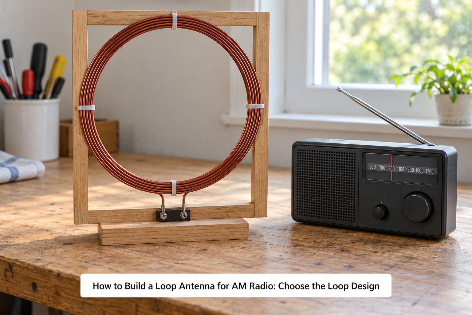
An unshielded air-core loop is a single loop of wire on an open frame. A shielded loop wraps that conductor in metal screen, which helps in a very electrically noisy room but costs you bandwidth and adds a tuning step. For a first build on the AM broadcast band, choose the unshielded air-core loop. You can measure it, move it and hear the difference immediately.
Windings on a ferrite rod concentrate the magnetic field and can give an effective receiving area far above their physical size, but the coupling to a receiver is weaker and adjustment is fussy. If you are scavenging, the ferrite route is the cheapest path to a working antenna.
| Loop | Turns | Approx. inductance | Capacitance at 520 kHz | At 1000 kHz | At 1710 kHz |
|---|---|---|---|---|---|
| Ferrite rod 150 mm, 60 turns | 60 | 60 µH | 1560 pF | 422 pF | 14 pF |
| Ferrite rod 300 mm, 250 turns | 250 | 300 µH | 312 pF | 84 pF | 3 pF |
| Air-core 300 mm loop | 10 | 98 µH | 956 pF | 258 pF | 9 pF |
| Air-core 600 mm loop | 6 | 79 µH | 1190 pF | 321 pF | 11 pF |
| Air-core 600 mm loop | 10 | 220 µH | 426 pF | 115 pF | 4 pF |
These are starting values for sizing a loop, not laboratory figures, and real inductances vary with turn spacing and wire diameter. Capacities below about 10 pF are hard to reach with real parts, which is why the higher-inductance rows are usually the practical ones. Cross-check your build against a loop calculator before you commit to a capacitor.
Keep the loop perimeter small. Keeping the perimeter under about one tenth of a wavelength is the usual rule for sharp, steerable receive nulls, and that means well under 60 m at AM frequencies, so frame size is not a constraint at this band.
How to Build a Loop Antenna for AM Radio: Assemble the Wire Loop
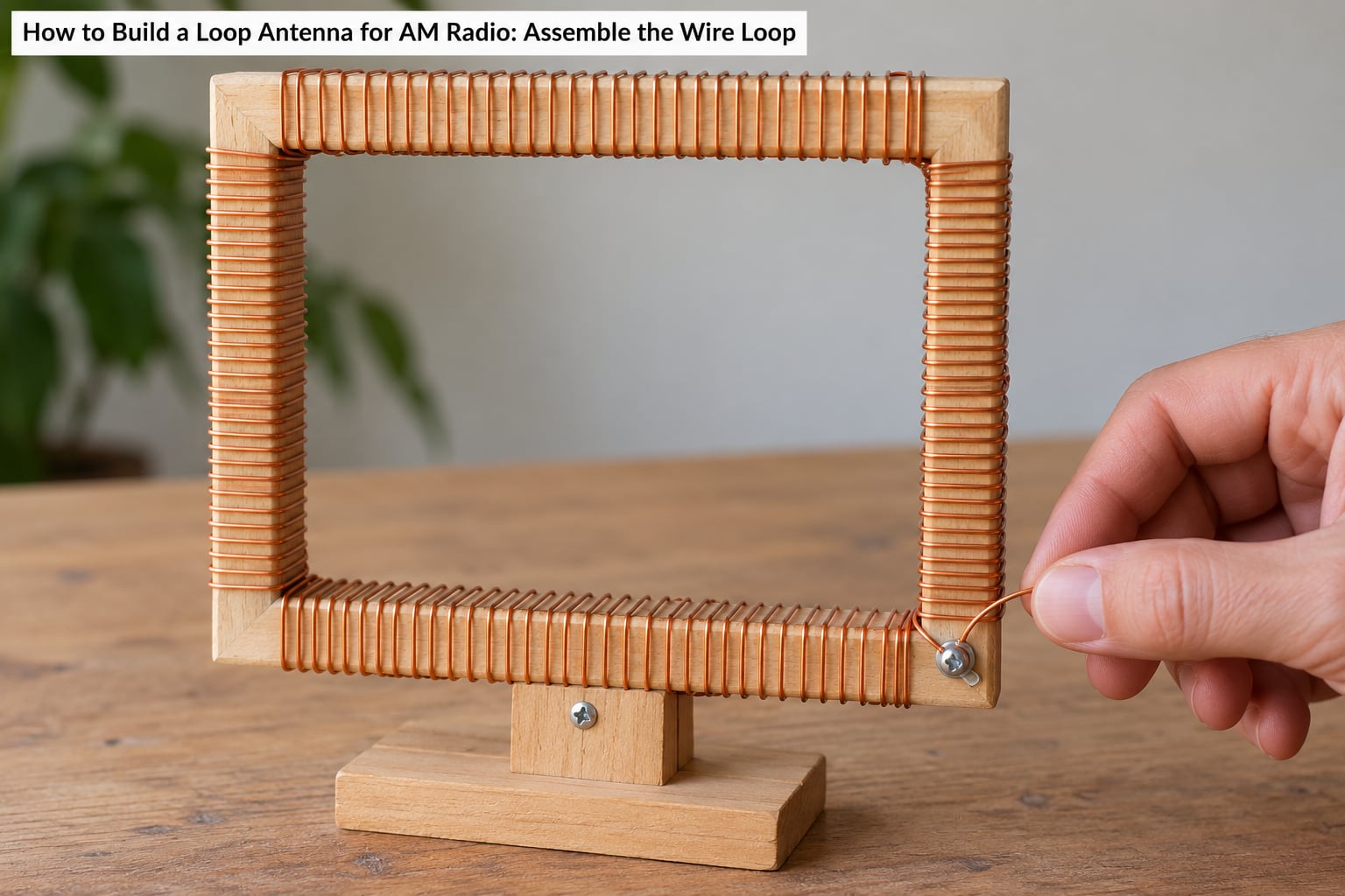
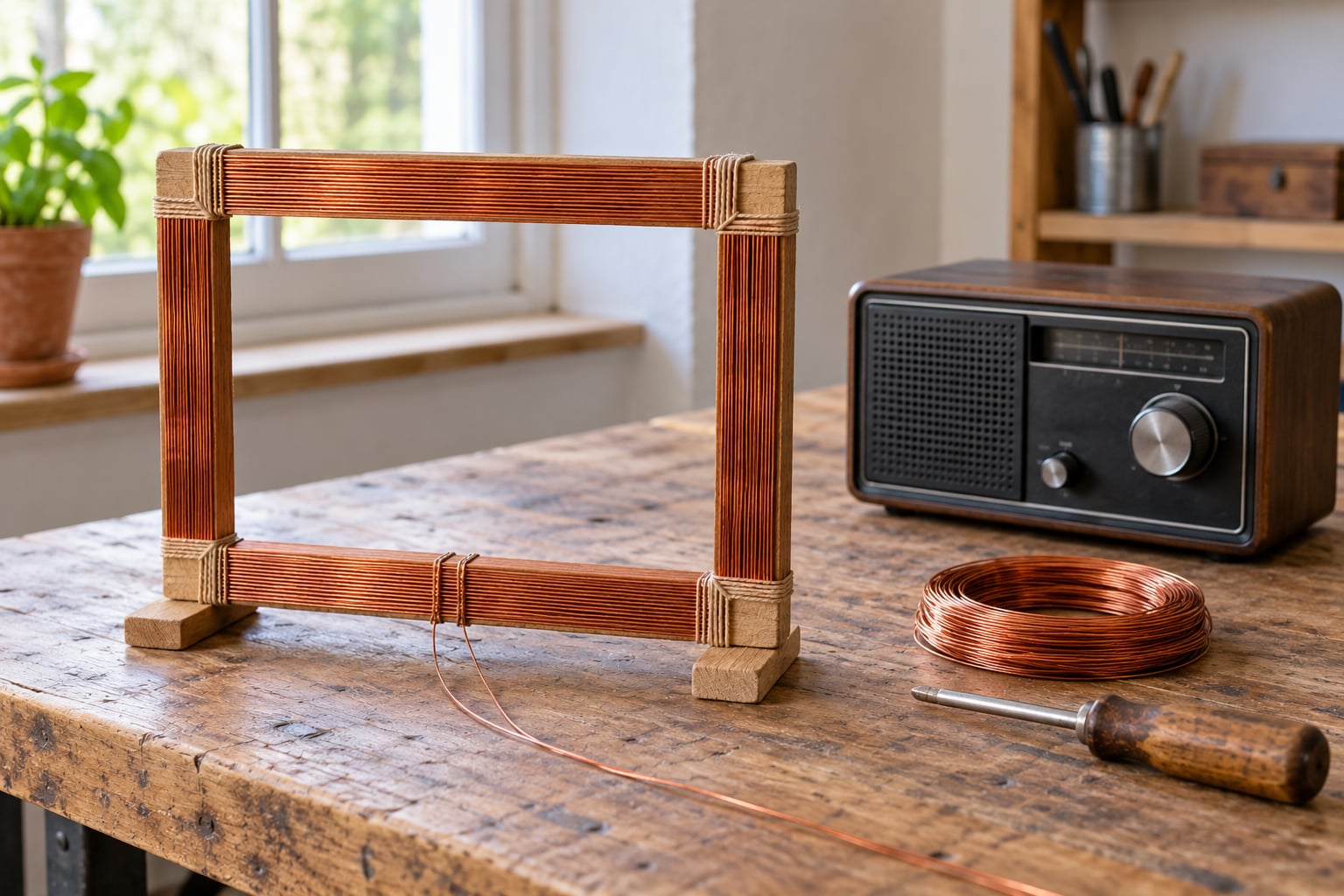
Wrap the turns evenly and side by side, tightening the tension as you go. Loose, sagging turns change the inductance and move your tuning point, which is the most common reason a hand-wound loop will not settle down. A dab of tape every few turns keeps the winding geometrically rigid.
Leave about 300 mm of extra wire at each end before you cut, and route those leads together rather than letting them spread apart. Widely separated leads act as an additional unbalanced antenna and will undo some of the noise rejection you built in.
If you want shortwave reception from the same loop, add tap points at roughly one third, two thirds and full turns and fit a rotary switch to select between them. That gives you different resonances without rewinding anything.
How to Build a Loop Antenna for AM Radio: Connect and Match the Antenna
Most receivers do not present a clean antenna input on the AM terminal, so coupling beats direct connection. Disconnect the internal ferrite or telescopic whip, connect your loop across the AM input terminals, and route the feedline away from the loop before it reaches the receiver. A loop wired straight into a high-impedance input with the feedline running back alongside it will pick up more noise than it rejects.
Matching still matters after that. The loop is a resonant circuit whose feedpoint impedance can run from tens of ohms to several hundred as you sweep the capacitor, and the receiver wants something it can see. Sweep the variable slowly, listen for the loudest point, and treat that as your match rather than trusting how the wiring looks.
Now the grounding question, which comes up constantly: leave the loop itself ungrounded. A receive loop is electrically a transformer secondary, and bonding one end to a mast or a water pipe lets the mast and house wiring carry ambient noise current straight into the winding. The receiver chassis already provides the reference it needs. Shielded versions can use an earth reference on the screen alone.
This build is receive-only. A tuned loop capacitor carries high RF voltage whenever the loop is driven, which is an RF burn risk, and none of the techniques here are a substitute for an antenna design and procedure suited to transmitting.
How to Build a Loop Antenna for AM Radio: Tune and Test Reception
Start with a baseline. Record what each of three or four stations sounds like on the supplied antenna, with the volume and AGC set the way you will keep them. Then swap to the loop and compare on the same settings.
Tune with the capacitor, not the receiver dial, and sweep slowly through the band to find the peak for each station. If your receiver has an S-meter, watch for the maximum. If not, listen for the point where the audio gets loud and clean and the noise floor stops dropping — a quiet spot with a clear station is better than a loud spot with the noise riding along.
Hand proximity is the thing that surprises people most. As a hand approaches the capacitor, the tuning drifts, because the high-Q circuit is physically sensitive to the added capacitance. Builders of transmitting loops solve this with motor-driven remote tuning for exactly that reason. For a receive loop, moving the capacitor onto a shaft and away from your hand is usually enough.
Orientation matters as much as tuning. A loop has deep nulls in the plane of its own wire, so rotate it and listen for a station to peak and vanish. Pointing a null at a noise source is the whole trick, and it works best when the interference comes from one place, like a switching supply, rather than being spread across the room.
Finally, move the loop an arm’s length from walls, metal and wiring before you judge it, and try it in a different room. Write down what you measured so you can tell an improvement from a change of mood.
Common Mistakes
Most disappointing loops fail on installation rather than on geometry. These are the ones I have seen repeatedly.
| Symptom | Likely cause | Fix |
|---|---|---|
| No improvement over the stock antenna | Feedline running alongside the loop, or the loop connected straight to the input | Separate the feedline, couple instead of hard-wire, and retest |
| Station gets stronger and the noise gets stronger with it | Unbalanced or open connection letting the loop radiate noise back into the room | Check continuity end to end and check that the loop is not a broken circuit |
| Tuning collapses when touched | High-Q circuit with the variable capacitor in reach of your hand | Move the capacitor to a shaft or panel mount |
| Constant hum | Ground or chassis connection on the loop, or the loop near a dimmer or supply | Disconnect any loop ground, then move or null the loop |
| Every station sounds alike, S-meter pegged | Far too much capacitance across the loop for the frequency being heard | Check the design table and use a smaller range or fewer turns |
| Works in one room, nothing in another | Loop too close to metal, wiring or a metal appliance | Keep it an arm’s length clear and rotate for a null |
| Extra capacitance from widely spaced leads | Feed leads spread apart instead of twisted | Twist and dress the leads together |
Two more worth naming. Buying a small transmitting mag loop and expecting AM broadcast reception will not work, because those kits are wound for the HF bands and the physics of radiation resistance scaling means a loop that size cannot couple usefully at 1 MHz. And check continuity before anything else, because a break in the winding looks exactly like a badly performing antenna.
Frequently Asked Questions
How big should an AM loop antenna be, and how many turns of wire?
For AM broadcast, a 300-600 mm (12-24 inch) frame with 6 to 10 turns covers the 520-1710 kHz band, and a 300 mm ferrite rod with roughly 250 turns works too. Bigger frames give broader bandwidth and easier tuning; smaller loops give sharper nulls but a narrower band. Pick from the sizing table and confirm with a loop calculator before you wind.
Does an AM loop antenna need a separate tuning capacitor?
For a clean, repeatable result, yes. A variable capacitor across the loop lets you resonate it at any station and recover the sensitivity a broadband loop gives up. The receiver’s own tuning capacitor can sometimes bring a loop to life, but it is switched in steps rather than swept, so you get a few usable bands instead of the whole dial. A 10-365 pF air variable is the usual choice.
Does a loop antenna need to be grounded?
No, and grounding one usually makes it worse. A receive loop is electrically a transformer secondary, so bonding it to a mast, a water pipe or a chassis lets noise current flow into the winding and ruins the rejection the loop was built for. The receiver’s own chassis is the reference the loop needs. With a shielded loop, the screen alone may be grounded.
Will an AM loop antenna work indoors and inside a car?
Indoors is exactly where loops help most, because the electrical noise from household devices is strong and a loop largely ignores it. In a car, an unshielded loop works well because the metal body is a shield. Place it near a window or away from the dashboard electronics, couple rather than hard-wire, and keep the feedline clear of the loop.
Why does my AM loop antenna still pick up noise?
Almost always the installation rather than the loop. Feedline running alongside the loop, a ground connection on the winding, or a capacitor within reach of your hand will all undo the benefit. Unshielded loops also cannot cancel electrical noise directly, which is why point-source interference sometimes needs a shielded loop and a null pointed at the source.
Can I use this loop antenna for transmitting?
Not as built. A tuned loop capacitor carries high RF voltage whenever the loop is driven, which is a genuine RF burn and shock hazard, and receive loops have very low efficiency. Transmitting at AM broadcast frequencies also requires a licence in most countries. This design is receive-only, and an FM or shortwave antenna is a different design problem that needs its own calculations.
Conclusion
Start with one thing: measure your frame, pick the row in the sizing table that matches it, and wind that many turns of magnet wire. Everything else in this build follows from that number, and a mistake here is expensive to unwind later.
Before you judge the results, verify your measurements, check continuity through the whole winding, and confirm the loop has no ground connection. Keep the capacitor away from your hand and the feedline away from the loop. Tune receive-only, compare honestly against the antenna your radio came with, and enjoy a quieter band on 2026.